Description
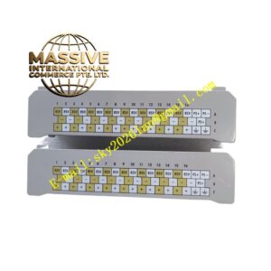
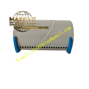
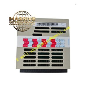
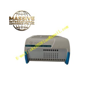
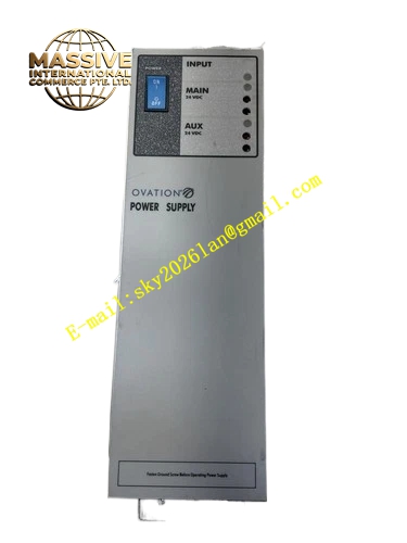
Emerson 1X00416H01
Technical Specifications
- Rated operating bus voltage: 24 VDC
- Continuous operating temperature: 0 °C‑60 °C
- Storage temperature: ‑40 °C‑85 °C
- Humidity: 5%‑95% non‑condensing
- Communication: proprietary DeltaV internal high‑speed bus protocol
- Supports hot‑swap for compatible DeltaV series modules
- Multi‑slot integrated layout for multi‑module expansion
Functional Features Integrated power distribution copper layers deliver 24 VDC power evenly to every slot. High‑speed signal traces realize real‑time inter‑module data communication. Built‑in hardware recognition logic lets DeltaV system auto‑detect model type and address information of inserted cards. Optimized layout delivers strong electromagnetic shielding performance, suppressing external high‑frequency noise and inter‑channel signal crosstalk. Hot‑swap compatible slots permit online card replacement without breaking cabinet‑level bus operation. Gold‑plated slot contacts maintain stable connection over long continuous industrial runtime.
Application Scenarios Applied in DeltaV main control cabinets, remote I/O cabinets and expansion cabinets within petrochemical plants, thermal power facilities, natural gas treatment sites, water‑supply‑and‑drainage automation projects, fine‑chemical pharmaceutical workshops, papermaking factories and metallurgy production lines. Used for all automation projects built upon Emerson DeltaV DCS platform.
Performance Parameters
- Microsecond‑level signal transmission delay
- Gold‑plated slot contact cycle life exceeds 1 000 000 insert‑remove operations
- Near‑zero communication packet loss under long‑term continuous running
- Full‑load capacity supports simultaneous operation of all populated slots
Material Composition Main substrate is high‑strength glass‑fiber‑reinforced epoxy board with good insulation, voltage‑resistance and anti‑aging performance. Slot contact pins adopt high‑purity copper base plus thick gold plating for low contact resistance and oxidation resistance. Metal shielding frame provides mechanical support and noise suppression. Positioning accessories use high‑temperature flame‑retardant engineering plastic. Internal power and signal traces follow industrial high‑precision PCB routing standards.
Structural Characteristics Whole unit is rectangular flat‑plate structure designed for horizontal installation inside standard DeltaV cabinet. Multiple module slots are orderly arranged with precise positioning and uniform spacing. Power distribution copper layers and signal traces are layered inside to achieve physical separation between power circuit and signal circuit. Ground terminals and mounting screw holes are reserved on both board ends for secure fastening and grounding. Mechanical strength resists vibration existing on industrial sites.
Working Principle 24 VDC power from power supply modules flows through internal copper distribution layers and reaches each independent slot to feed plug‑in hardware. Signal traces construct high‑speed data links connecting controllers, I/O modules and communication boards. Once a module seats fully, backplane completes hardware registration and identification. Control commands, field acquisition data and diagnostic messages travel across backplane bus to realize centralized cabinet‑wide data management.
Installation Requirements Mount horizontally inside matching DeltaV cabinet. Tighten fixing screws evenly to prevent PCB deformation. Connect both‑end grounding terminals reliably to cabinet grounding bus bar for shielding performance. Do not bend, scratch or squeeze PCB surface and slot pins during installation. Maintain cabinet sealing to block dust, moisture and corrosive vapors invading connector pins. Keep precise alignment during module insertion.
Use Precautions Cut off full cabinet power before plugging non‑hot‑swap modules. Prevent metal fragments and wire scraps from dropping into slot gaps which may trigger short‑circuit or signal failure. Avoid direct hand‑touch toward gold‑plated contact pins; sweat and grease produce oxidation‑induced poor contact. Periodically inspect slots for dust accumulation and oxidation signs. Never cut or modify original backplane circuit traces.