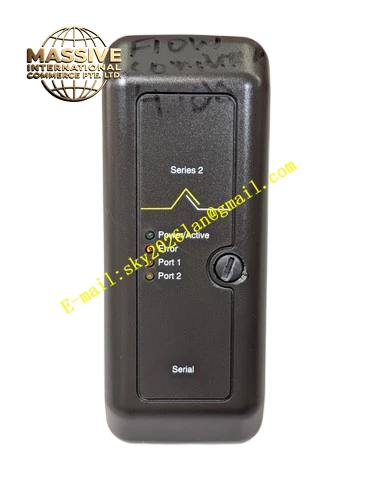
Description
Technical Specifications
- Multiple module slots for machinery protection modules
- Rated operating voltage: 24VDC
- Operating temperature: 0°C to 60°C
- Storage temperature: -40°C to 85°C
- Ambient humidity: 5% to 95% non-condensing
- Gold plated signal traces and connector contacts
- Supports hot swap of individual plug-in modules
Functional Features Distributes DC power from rack power supply to each module slot. Transmits internal bus communication signals between all rack modules. Provides mechanical positioning and supporting function for plug-in modules. Gold-plated contacts maintain low contact resistance and anti-oxidation performance. Supports redundant module installation and hot swap operation. Optimized PCB layout reduces bus crosstalk between adjacent slots.
Application Scenarios Used as rear backplane of machinery protection racks for steam turbines, compressors and large rotating pumps in power, petrochemical and metallurgical industries. Accommodates vibration monitoring, speed monitoring, relay output and main processing modules.
Performance Parameters
- Low impedance power distribution traces
- Low signal attenuation on internal communication bus
- Long service life of gold-plated connector contacts
- High mechanical stability under industrial vibration
Material Composition Multi-layer high-precision PCB substrate. Copper traces with gold plating on contact areas. Reinforced glass fiber material for mechanical rigidity. Metal grounding frame for electromagnetic shielding. High-strength plastic positioning guides for module insertion.
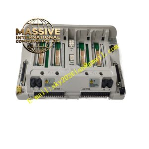
Structural Characteristics Horizontal passive backplane installed at the rear of machinery protection rack. Multiple slot connectors arranged in parallel along the board. Built-in power bus and signal bus layers inside PCB. Mechanical guide grooves help align plug-in modules during insertion. Mounting holes secure backplane firmly to rack frame.
Working Principle DC power from rack power supply module is transmitted through backplane power traces to each module slot. Internal communication bus traces connect all module slots together to realize data exchange between modules. When modules are inserted into slots, backplane connectors establish electrical connection automatically. The backplane only transmits power and signals and does not execute data processing or logic calculation.
Installation Requirements Mount the backplane securely onto the metal rack frame using matching fasteners. Ensure all mounting screws are tightened evenly. Keep backplane surface clean and free of metal debris. Route internal rack wiring according to the official drawing. Verify grounding connection of backplane frame.
Use Precautions Cut off all rack power before installing or removing the backplane. Do not scratch gold-plated connector contacts. Prevent metal fragments falling onto PCB traces. Do not insert damaged modules into backplane slots. Inspect connector contacts periodically for dust and oxidation.