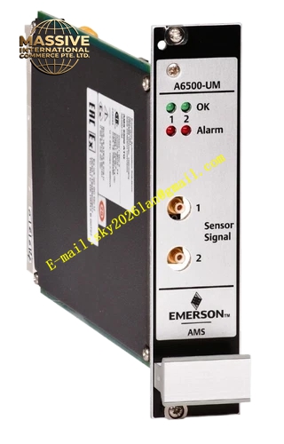
Description
Emerson A‑6500‑UM
Technical Specifications: Module power supply: 24 VDC supplied by system rack backplane Input signal types: eddy‑current probe signal, accelerometer signal, velocity sensor signal, tachometer pulse signal Galvanic isolation between each channel: built‑in channel‑to‑channel isolation circuit Analog output signal: 4‑20 mA proportional output Relay alarm output: alert relay and danger trip relay Operating temperature: 0 ℃ to 60 ℃ Storage temperature: ‑40 ℃ to 85 ℃ Relative humidity: 5%‑95% non‑condensing
Functional Features: Multi‑sensor‑type adaptive input circuit. Independent alert and danger threshold setting for each measuring channel. Adjustable alarm delay time suppresses transient false alarm. Hardware‑based trip output meets machinery‑protection safety requirements. Buffered raw signal output facilitates on‑site oscilloscope debugging. Built‑in sensor cable breakage and short‑circuit diagnostic function. Hot‑swap module design supports online replacement. System bus uploads real‑time measurement value and fault information.
Application Scenarios: Integrated condition monitoring and protection for steam turbine, gas turbine, centrifugal compressor, large‑size fan, water‑feed pump in power and petrochemical industry, rotating‑machinery safety interlock protection for metallurgical plant.
Performance Parameters: Measurement accuracy: ±0.5% full scale Relay contact capacity: resistive load maximum 250 VAC / 3 A Vibration resistance: 10 Hz‑150 Hz, 0.5 g Shock resistance: 10 g peak, 11 ms MTBF value: 224000 hours
Material Composition: Module housing: UL94‑V0 flame‑retardant thermoplastic. Internal printed circuit board: FR‑4 glass‑fiber epoxy substrate. Backplane connector contact pins: gold‑plated copper alloy. Relay components are sealed‑package industrial‑grade relays. Module locking mechanism adopts reinforced engineering plastic.
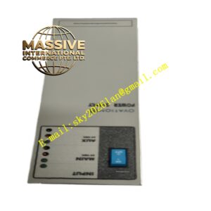
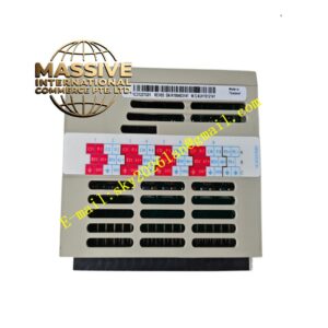
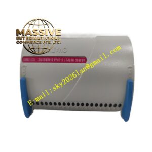
Structural Features: 3U Euro‑card plug‑in module structure, suitable for AMS6500 standard rack installation. Two‑side locking latches fix module inside rack. Front panel is equipped with multiple LED indicator lights for power, alarm, channel fault status. Rear‑side multi‑pin gold‑plated connector connects rack backplane power supply and communication bus. Upper housing surface is provided with ventilation slots for passive heat dissipation.
Working Principle: Signals from different types of field sensors access module input terminals. Internal signal‑conditioning circuit processes and filters raw sensor signals. Measurement circuit converts analog physical‑quantity signal into digital value. Software compares measured value with pre‑configured alert and danger threshold. When measured value exceeds threshold, corresponding relay action outputs alarm or trip interlock signal. Real‑time data transmits to upper system through rack backplane bus.
Installation Requirements: Insert module into designated slot of AMS6500 rack. Fasten side locking latches completely. Field sensor signal cables use shielded twisted‑pair wiring, single‑point grounding at cabinet side. Separate sensor signal cables and high‑voltage power cables. Cut off rack power supply before module plug‑in and removal.
Precautions for Use: Do not change threshold parameter configuration randomly during equipment running. Wear anti‑static wristband when touching module internal circuit. Inspect ventilation slot dust accumulation status in regular maintenance. Do not install in environment with corrosive gas and conductive dust. Replace module immediately if front‑panel indicator appears abnormal and cannot recover.