Description
Emerson A6110‑9199‑00001
Technical Specifications: Number of measuring channel: two independent differential input channels Matched sensor: PR6422, PR6423, PR6424, PR6425 eddy‑current probe with CON series converter Sensor power supply output: ‑26.7 VDC nominal value, each channel maximum output current 35 mA Input impedance: greater than 100 kΩ Frequency response: low‑cutoff 1 Hz or 5 Hz optional; high‑cutoff 50‑2000 Hz adjustable Analog output: each channel supports 4‑20 mA and 0‑10 V proportional output Alarm delay setting range: 0‑5 s adjustable Module power supply: 24 VDC from rack backplane Operating temperature: 0 ℃‑60 ℃ Storage temperature: ‑40 ℃‑85 ℃
Functional Features: Two fully‑independent measuring channels can work separately or operate in combined mode. Galvanic isolation exists between two channels. Alert and danger two‑level alarm threshold can be set independently. Remote trip bypass and limit‑multiplication function supported. Buffered raw dynamic‑signal output for field test instrument connection. Comprehensive self‑diagnosis covers sensor cable open‑circuit, short‑circuit, module hardware fault. Hot‑swap module allows online replacement without rack power‑off. LED indicators display channel working, alarm and fault status.
Application Scenarios: Shaft relative vibration monitoring and protection for steam turbine, gas turbine, centrifugal compressor, large‑size water‑feed pump, axial‑flow fan in power plant and petrochemical plant.
Performance Parameters: Measurement linearity error: ≤ ±1% full‑scale range Typical power consumption: ≤ 6 W Vibration resistance: 10 Hz‑150 Hz, 0.5 g Shock resistance: 10 g peak acceleration, 11 ms duration MTBF value: 218000 hours
Material Composition: Module outer shell: UL94‑V0 flame‑retardant thermoplastic material. Main circuit board: FR‑4 glass‑fiber epoxy printed substrate. Backplane connector pins: gold‑plated copper alloy. Industrial‑grade sealed relays for alarm‑trip output. Module locking latches adopt high‑strength reinforced engineering plastic.
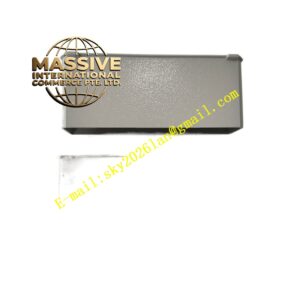
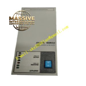
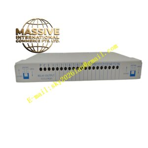
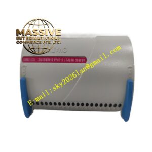
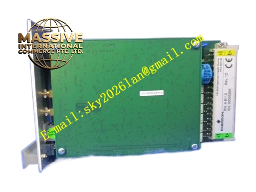
Structural Features: 3U height Euro‑card plug‑in module, single‑slot installation inside AMS6500 rack. Two‑side mechanical locking buckles for rack fixing. Front‑panel layout contains group of LED status indicator lights. Rear‑side multi‑pin gold‑plated connector connects rack backplane power supply and system communication bus. Ventilation grille distributed on upper shell surface for passive heat dissipation.
Working Principle: Voltage signal output by eddy‑current converter enters two input channels of module. Internal filter circuit configures cutoff frequency according to field‑equipment rotating‑speed characteristic. Circuit converts vibration‑related voltage variation into displacement measurement value. Internal logic compares real‑time measured value with pre‑configured alert and danger threshold. Once threshold condition satisfies, corresponding relay actuates and outputs alarm or trip signal. Measurement data uploads to host monitoring system through rack bus.
Installation Requirements: Insert module into AMS6500 standard rack designated slot. Lock two‑side latches to guarantee reliable backplane connector contact. Sensor signal cables adopt shielded twisted‑pair, shield layer single‑point grounding inside cabinet. Keep signal cables far away from high‑voltage and frequency‑converter power cables. Cut off rack power before inserting or pulling‑out module.
Precautions for Use: Sensor measuring chain must complete whole‑set matching calibration before putting into service. Wear anti‑static wristband in maintenance operation. Do not adjust internal hardware jumpers randomly. Clean dust on ventilation grille during regular overhaul. Stop module application when shell deformation or burn trace occurs.