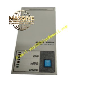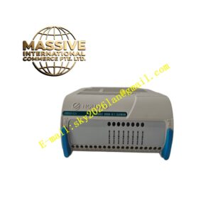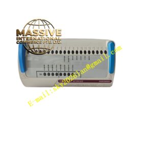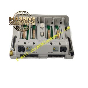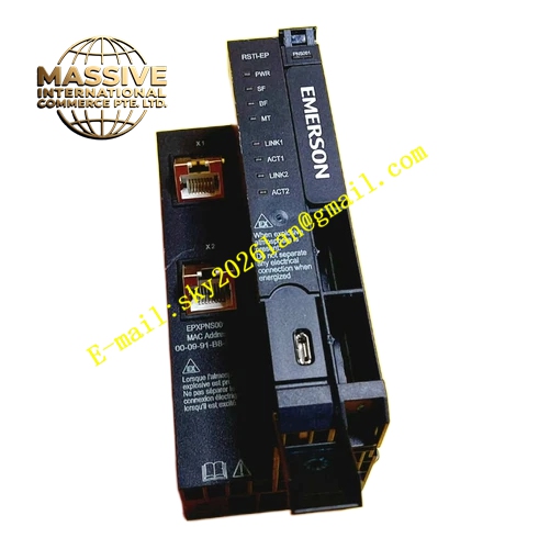
Description
Emerson A6120
Technical Specifications
- Number of relay output channels: 4 relay channels
- Relay contact rating: 250VAC / 5A
- Operating temperature: 0°C to 60°C
- Storage temperature: -40°C to 85°C
- Ambient humidity: 5% to 95% non-condensing
- Relay state feedback function
- Isolation between each relay channel
Functional Features Independent electromagnetic relay for each output channel. Relay contacts support normally open and normally closed configurable mode. Hardware fast trip output responds quickly to protection commands. Built-in relay self-diagnosis monitors relay coil and contact state. Front panel LED indicators show relay status, alarm and trip state. Supports hardwired interlock connection for machinery protection system.
Application Scenarios Installed in machinery protection racks of steam turbines, compressors and large pumps in power and petrochemical industries. Output trip and alarm relay signals for rotating machinery protection.
Performance Parameters
- Relay mechanical life reaches 10 million operations
- Fast relay actuation response time
- Stable contact performance under industrial vibration
- Surge suppression for relay coil circuit
Material Composition Flame-retardant industrial PCB substrate. Industrial electromagnetic relay components. Surge absorption components for relay coil protection. Gold-plated backplane connector pins. Flame-retardant plastic front panel and terminal blocks.
Structural Characteristics Standard rack plug-in card design. Front panel integrates wiring terminals and LED status indicators. Mechanical locking buckle prevents vibration induced loosening. Each relay channel is arranged in separated area to reduce cross-channel interference.
Working Principle Alarm or trip commands from monitoring modules are transmitted to A6120 module through rack backplane. Internal drive circuit controls energization or de-energization of relay coil. Relay contacts close or open to switch external hardwired trip or alarm circuits. The module continuously monitors relay working state and reports relay fault information to machinery protection system.
Installation Requirements Insert module into designated slot of machinery protection rack and lock buckle. Separate field trip wiring from sensor signal cables. Tighten terminal block screws to ensure reliable contact. Complete protective grounding for the whole rack.
Use Precautions Do not exceed rated contact load of relays. Install external surge suppression components when switching inductive loads. Test relay channels completely after installation. Replace module once relay contact adhesion occurs.