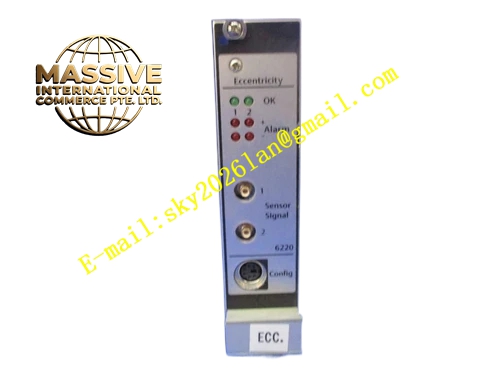

Description
Emerson A6220
Technical Specifications
- Monitoring channel quantity: 4 independent vibration input channels
- Supported sensors: eddy‑current displacement probe, piezoelectric acceleration sensor
- Vibration measuring full‑scale range: 0 μm‑250 μm
- Operating temperature: 0 °C‑60 °C
- Channel isolation rating: 1000 V
- Signal sampling rate: maximum 25.6 kHz high‑speed sampling
Functional Features Captures real‑time vibration amplitude, waveform and spectrum data, detecting subtle mechanical vibration variations. Each channel supports independent configurable alarm threshold and trip threshold. Hardware‑level fast trip output guarantees rapid response for machine protection. Built‑in sensor fault detection identifies probe failure or cable break. Collected vibration data uploads to host monitoring system for historical trend recording and equipment health analysis. Channel‑isolated design restrains cross‑channel noise coupling.
Application Scenarios Machine protection application for steam turbines, centrifugal compressors, large‑size induced draft fans and heavy‑duty centrifugal pumps in power plants and petrochemical refineries. Installed inside dedicated machinery‑protection cabinets for rotating equipment condition monitoring and safety interlock protection.
Performance Parameters
- Measurement accuracy reaches ±1 % of full‑scale reading
- Hardware trip response time less than 10 ms
- High sampling rate captures transient vibration impulse events
- Diagnostic function reliably identifies open sensor cable and probe fault
Material Composition Inner circuit board is high‑precision industrial flame‑retardant PCB populated with high‑resolution analog‑to‑digital conversion chips. Metal shielding shell suppresses external electromagnetic noise. Backplane connector contacts are gold‑plated to secure stable signal transmission. Components satisfy high‑reliability long‑term continuous‑operation standards for machinery‑protection systems.
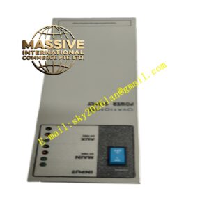
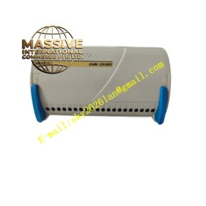
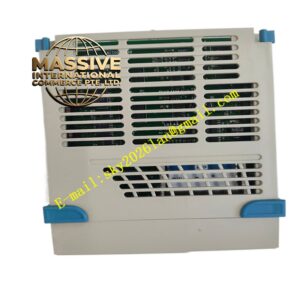
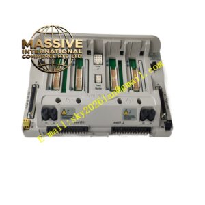
Structural Characteristics Standard rack‑mount plug‑in card structure fitting dedicated machinery‑protection rack slots. Front panel arranges LED indicator lamps showing channel status, alarm state and trip condition. Internal metal shielding layer wraps analog signal acquisition circuit section to block outside electromagnetic interference. Mechanical locking structure prevents displacement under site vibration.
Working Principle Weak analog vibration signal coming from field sensors enters module internal circuits. Signal conditioning circuits implement amplification, filtering and noise elimination. Analog‑digital converter converts analog physical vibration value into digital measurement data. Internal logic compares real‑time measured value with user‑configured alarm and trip thresholds. If measurement exceeds safety setting, hardware circuit activates alarm relay or trip output signal to trigger safety protection actions for rotating equipment. Meanwhile diagnostic logic checks sensor loop integrity continuously.
Installation Requirements Install module inside dedicated machinery‑protection rack cabinet. Sensor signal cables must route separately from high‑power motor cables and inverter power lines. Sensor cable shielding applies single‑end grounding method following system manual. Cabinet installation location shall keep distance away from large‑capacity contactors and high‑frequency interference sources. Ensure cabinet cooling ventilation works normally.
Use Precautions Complete sensor and module calibration before commissioning and putting machinery‑protection system online. Do not arbitrarily modify alarm and trip threshold parameters during equipment running. Carry out regular inspection for sensor cable insulation integrity. Replace module once permanent hardware fault appears in self‑diagnosis report.