Description
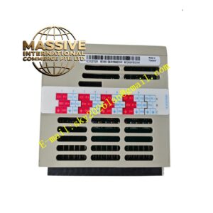
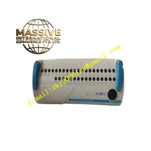
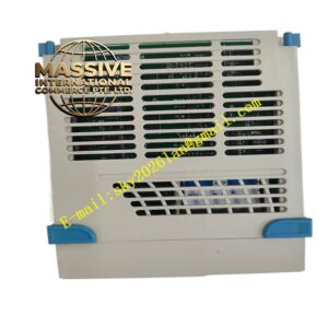
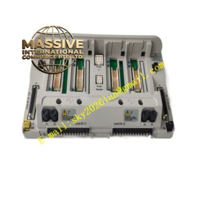
Emerson A6312
Technical Specifications: Redundant power‑input: two independent 24 VDC input terminals Input voltage allowable range: 20‑28 VDC Output power supply: multiple groups of isolated 24 VDC bus inside rack Module width: 6 TE standard Euro‑card dimension Isolation between input and output: galvanic isolation Power‑failure alarm output: dry‑contact relay output Operating temperature: 0 ℃‑60 ℃ Storage temperature: ‑40 ℃‑85 ℃ Relative humidity: 5%‑95% non‑condensing
Functional Features: Dual redundant power‑input with diode‑auctioneering backup. When one path of input power fails, another path takes over load without power‑supply interruption. Built‑in voltage monitoring circuit for output bus. Dry‑contact relay outputs power‑supply‑fault alarm signal. LED indicator lights display working status of two input power‑supply circuits. DIN 41612 standard rear‑connector connects rack internal power‑distribution bus. Over‑current protection circuit protects internal circuit from short‑circuit damage.
Application Scenarios: Power‑supply supporting unit for AMS6500 machinery‑protection rack in thermal power plant, petrochemical plant, metallurgical plant, providing stable power for vibration‑monitor and position‑monitor modules inside rack.
Performance Parameters: Maximum output load capacity matches full‑slot AMS6500 rack load demand Vibration resistance: 10 Hz‑150 Hz, 0.5 g Shock resistance: 10 g peak acceleration, 11 ms duration MTBF value: 232000 hours
Material Composition: Module front‑panel: flame‑retardant reinforced plastic. Internal circuit board: FR‑4 thickened glass‑fiber epoxy printed board. Rear‑side connector: DIN41612 standard gold‑plated connector. Power‑relay components are industrial‑grade sealed relays. Internal power‑semiconductor components have heat‑dissipation structure.
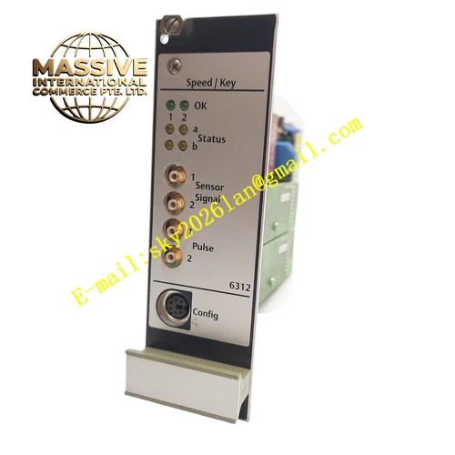
Structural Features: Euro‑card 6 TE width plug‑in module structure, installed on left‑most slot of AMS6500 rack. Front‑panel layout contains power‑input wiring terminals and LED working‑status indicator lights. Rear‑side DIN standard multi‑pin connector connects rack internal power‑distribution backplane. Metal heat‑dissipation structure arranged inside module for power‑device heat dissipation.
Working Principle: Two independent external 24 VDC power sources connect to two‑way input terminals of module. Internal diode‑auctioneering circuit completes redundant power‑supply switching. Stable 24 VDC power distributes to each module slot through rack internal power‑bus. Voltage‑monitoring circuit continuously detects output‑bus voltage. When any input‑power path loses voltage or output‑bus voltage deviates from normal range, fault‑relay acts and outputs remote power‑failure‑alarm dry‑contact signal.
Installation Requirements: Insert A6312 module into left‑most dedicated power‑slot of AMS6500 rack. Guarantee reliable contact between rear‑side connector and rack backplane. Two‑way redundant power supply adopts completely independent external power source. Tighten power‑input terminal screw torque within 0.6‑0.8 N·m. Cut off all external input power before wiring operation.
Precautions for Use: Do not use single power‑source parallel output as two‑way redundant input. Wear anti‑static wrist‑band during maintenance work. Regularly inspect terminal‑screw fastening status. Keep ventilation path of internal heat‑dissipation structure unobstructed. Stop module operation when burn‑trace appears on front‑panel or internal components.