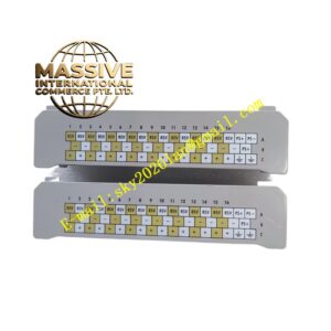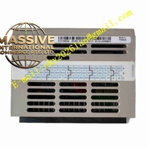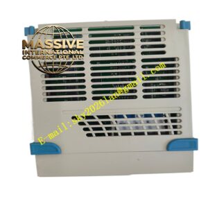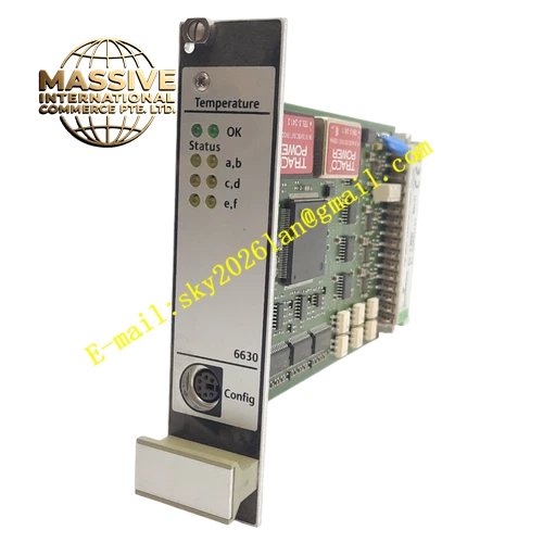
Description
Emerson DB1-1
Technical Specifications
- Input interface: matched for eddy current probe with extension cable
- Output signal: linear analog voltage signal
- Operating temperature: 0°C to 60°C
- Storage temperature: -40°C to 85°C
- Ambient humidity: 5% to 95% non-condensing
- Built-in cable length compensation circuit
- Probe cable impedance matching function
Functional Features Generates stable high-frequency excitation signal for eddy current probes. Implements automatic impedance compensation for matched probe extension cables. Converts probe coil impedance changes into linear analog output voltage. Continuous probe and cable fault detection identifies open circuit, short circuit and cable damage. Front panel LED lamps show power status and sensor loop fault alarms. Supports multiple probe models within the compatible product series.
Application Scenarios Deployed in machinery protection cabinets for steam turbines, centrifugal compressors, large induced draft fans and heavy-duty process pumps in power plants and petrochemical refineries. Works together with eddy current probes to monitor shaft relative vibration and axial displacement.
Performance Parameters
- High linearity of output voltage corresponding to probe gap
- Low temperature drift for long-term continuous measurement
- Stable excitation signal output under industrial interference
- Fast response to rapid gap variation between probe and metal shaft
Material Composition Industrial flame-retardant printed circuit board with high-frequency signal conditioning chips. Metal shielding shell isolates external electromagnetic noise. Gold-plated backplane connector pins maintain reliable signal transmission. Flame-retardant plastic front panel with indicator windows and wiring terminals.
Structural Characteristics Standard rack mount plug-in card design for machinery protection racks. Front panel integrates wiring terminals for probe cable connection and status LEDs. Mechanical locking buckle secures the module against vibration movement. High-frequency signal circuits are wrapped by internal shielding layers to reduce signal distortion.
Working Principle The module produces high-frequency alternating excitation signal and sends the signal through extension cable to the coil inside eddy current probe tip. Eddy current induced on metal shaft surface changes probe coil impedance. The driver module detects impedance variation, applies cable length compensation, and converts the variation into continuous analog voltage signal. The analog output signal reflects the gap distance between probe tip and shaft surface. Built-in circuit monitors the integrity of probe and cable loop continuously.
Installation Requirements Insert the module into the designated slot of machinery protection rack and lock the buckle. Route probe extension cables separately from high-power inverter cables. Follow single-end grounding rules for probe cable shielding. Ensure cabinet cooling air flow maintains normal operating temperature.
Use Precautions Match the probe and extension cable model strictly before commissioning. Complete gap calibration after probe installation. Avoid sharp bending of probe cables. Do not connect non-compatible eddy current probes to this driver module.