Description
Emerson EP-4164
Technical Specifications: Power supply: 24 VDC Input channel: 32 digital input channels Output channel: 32 digital output channels Signal type: 24 VDC sinking/sourcing signal Galvanic isolation: 1500 VAC between field side and control side Operating temperature: 0 ℃ to 55 ℃ Storage temperature: -40 ℃ to 85 ℃ Relative humidity: 5% to 95% non-condensing
Functional Features: Each channel equipped with independent surge suppression circuit. LED status indicator for every input and output channel. Short-circuit protection for each output channel. Hot-swap capability supports online module replacement. Built-in self-diagnosis detects output short circuit and channel circuit fault. Electronic module identification for automatic system recognition. Supports high-speed trigger signal capture for motion position latch.
Application Scenarios: Limit switch signal collection for automatic machine tools, solenoid valve output control for packaging machinery, sensor signal acquisition for material handling equipment, interlock signal processing for printing equipment, safety door and emergency stop signal detection of automated assembly line.
Performance Parameters: Input response time: less than 100 μs Output maximum load current per channel: 0.5 A Vibration resistance: 10 Hz to 150 Hz, 0.5 g Shock resistance: 10 g peak acceleration, 11 ms duration MTBF value: 201000 hours
Material Composition: Module housing: UL94-V0 flame-retardant thermoplastic. Main PCB: FR-4 glass fiber epoxy printed board. Backplane connector pins: gold-plated copper alloy. Terminal blocks use nickel-plated brass. Side locking latches: reinforced engineering plastic.
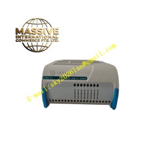
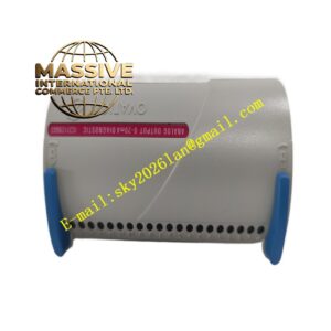
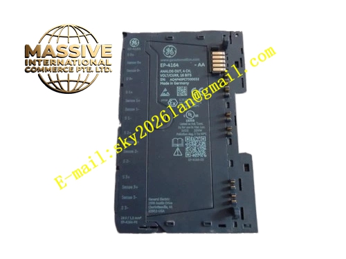
Structural Features: Standard rack plug-in module. Two side locking buckles for rack mounting. Front panel arranged with channel LED indicators and terminal block area. Ventilation slots on top shell for passive heat dissipation. Rear multi-pin gold-plated connector docks rack backplane power and motion bus.
Working Principle: Field digital input signals pass through isolation and protection circuit, then transmit to internal input chip. The module uploads switch status data to motion processor via rack backplane bus. Motion processor sends digital output commands to this module through backplane bus. Internal drive circuit converts command signal into 24 VDC output signal to drive field solenoid valves or relays. Diagnosis circuit monitors each channel state continuously.
Installation Requirements: Insert module into designated I/O slot of motion control rack and lock side latches. Field signal wiring uses shielded cable. Separate signal cables and high-power motor cables. Tighten terminal screws with specified torque. Cut off rack power before module installation or removal.
Precautions for Use: Do not connect AC high voltage signal to digital terminals. Wear anti-static wristband in maintenance work. Check terminal screw tightness periodically. Keep ventilation slots free of dust. Stop using module if output channel suffers permanent damage.