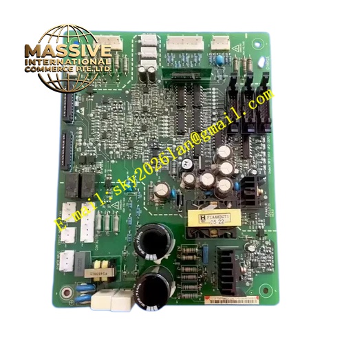
Description
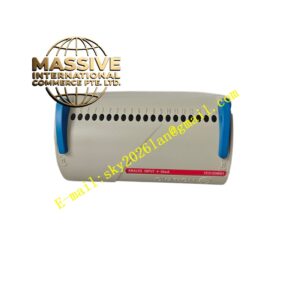
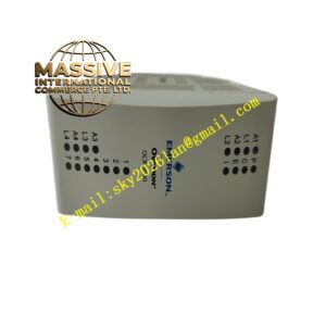
Emerson F1A4M3GR1
Technical Specifications: Control power supply: 24 VDC Analog signal range: 0-10 V, 4-20 mA Digital signal level: 24 VDC discrete signal Galvanic isolation: 1500 VAC between field side and control board side Operating temperature: 0 ℃ to 55 ℃ Storage temperature: -40 ℃ to 85 ℃ Relative humidity: 5% to 95% non-condensing
Functional Features: Signal level conversion for multi-type field sensors. Independent surge suppression and EMI filtering for each signal channel. Galvanic isolation blocks interference transmission between field and internal control circuit. Digital signal input and output processing. Terminal test points for on-site signal measurement. LED indicators for each channel signal status.
Application Scenarios: Interface board for large motor drive unit, power plant auxiliary drive equipment signal interface, industrial rectifier equipment signal acquisition board, compressor drive unit external signal connection board, power conversion equipment field signal adapter.
Performance Parameters: Analog signal transmission accuracy: ±0.15% full scale Vibration resistance: 10 Hz to 150 Hz, 0.5 g Shock resistance: 10 g peak acceleration, 11 ms duration MTBF value: 182000 hours
Material Composition: PCB substrate: FR-4 glass fiber epoxy printed board. Connector pins: gold-plated copper alloy. Signal terminals: nickel-plated brass. Protection components are transient voltage suppression diodes and gas discharge tubes. Board fixing hardware uses stainless steel screws.
Structural Features: Rectangular printed circuit board. Edge connectors for connecting main control board. Screw terminal blocks arranged on one side for field signal wiring. Component partition layout separates analog signal area and digital signal area. Installation holes on four corners for screw fixing on chassis.
Working Principle: Field analog and digital signals connect to terminal blocks on the board. Signals pass through filter and surge protection circuit, then go through isolation circuit. Signal level conversion circuit adjusts signal to matched level for main control board. The board transmits internal equipment status signal to external system through output terminals.
Installation Requirements: Fix board on designated chassis position with stainless steel screws. Reserve clearance for heat dissipation. Field signal wiring uses shielded twisted pair cable. Separate signal cables and high voltage power cables. Cut off all power before wiring or board replacement.
Precautions for Use: Do not connect high voltage signal to signal terminals. Wear anti-static wristband during maintenance. Inspect terminal screw tightness periodically. Do not install in environment with corrosive gas. Replace board if signal channel suffers permanent damage.