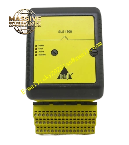
Description
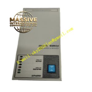
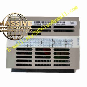
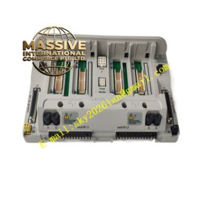
Emerson K2201X1-HA1
Technical Specifications: Operating voltage range: 24 VDC nominal, 19.2 VDC to 30 VDC working range. Signal channel quantity: Matches corresponding Ovation I/O card channel definition. Insulation voltage: 1500 VAC between field side and logic side. Operating temperature range: 0 ℃ to 60 ℃. Storage temperature range: -40 ℃ to 85 ℃. Relative humidity: 5% to 95% non-condensing.
Functional Features: It provides screw-type wiring terminals for field cable connection. Built-in surge suppression components protect control cards from transient voltage spikes. It supports hot-swappable matching with Ovation I/O modules. Integrated circuit status test points allow on-site maintenance personnel to detect signal quality without disconnecting wiring. It adopts channel independent wiring design to reduce cross-channel signal interference.
Application Scenarios: Thermal power generation plant DCS control systems, petrochemical production control cabinets, water treatment automatic control systems, metallurgy process monitoring, pulp and paper production line control, and other heavy industrial continuous process control projects.
Performance Parameters: Contact resistance of wiring terminals: less than 10 milliohm. Signal bandwidth: DC to 10 kHz. Shock resistance: 10g peak acceleration, 11 ms duration. Vibration resistance: 10 Hz to 150 Hz, 0.5g. MTBF value reaches more than 200000 hours under standard industrial environment.
Material Composition: Terminal base body uses high-strength flame-retardant thermoplastic material, UL94-V0 fire rating. Terminal screws are nickel-plated brass. Internal circuit board adopts FR-4 glass fiber epoxy substrate. Surge protection components are encapsulated in epoxy resin. Metal fixing clips are stainless steel.
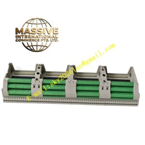
Structural Features: Standard DIN rail mounting structure. The upper part has card slot for plugging I/O card. The lower part arranges screw terminals in rows. Marking areas are reserved on the surface for channel number labeling. Built-in positioning buckle ensures accurate alignment with I/O card. The shell has dust-proof grooves to reduce dust accumulation inside the assembly.
Working Principle: Field instrument signals enter through external cables connected to screw terminals. Signals pass through built-in surge protection circuits and filtering circuits, then transmit to the corresponding I/O card plugged on the base. The card converts analog or digital signals into digital data for controller processing. The power supply for the signal loop is also distributed through the power circuit on this terminal base.
Installation Requirements: Install on standard 35mm DIN rail inside the control cabinet. Keep 25mm vertical clearance above and below the module for heat dissipation. Keep a minimum 10mm gap between adjacent terminal assemblies. Field cables and control internal cables must be routed in separate cable trays. Tighten terminal screws with torque of 0.6 N·m to 0.8 N·m. Complete power-off check before wiring.
Precautions for Use: Do not install in environments with corrosive gas, conductive dust or oil mist. Do not exceed the rated voltage and current of each channel. Check terminal screw tightness regularly during scheduled maintenance. Disconnect all field wiring before removing the terminal base. Static discharge protection wristband must be worn when touching internal circuits. Avoid pulling field cables directly to prevent terminal deformation.