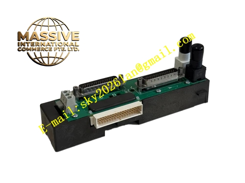
Description
Emerson KJ4001X1‑BH1
Technical Specifications
- Slot Quantity: 4 independent I/O module mounting slots
- LocalBus Input Voltage: 12.6 VDC, maximum total load current 4 A
- Bussed Field Power Rating: maximum 30 VDC, aggregated 3.2 A
- Operating Ambient Temperature: ‑40 °C ~ +70 °C
- Storage Temperature: ‑50 °C ~ +85 °C
- Relative Humidity: 5 %‑95 %, non‑condensing
- Airborne Contaminant Grade: ISA‑S71.04‑1985 Class G3
- Protection Rating: IP20
- Shock Resistance: 10 g half‑sine pulse, 11 ms duration
- Vibration Resistance: 1 mm peak‑to‑peak amplitude 2‑13.2 Hz; 0.7 g acceleration 13.2‑150 Hz
- Installation Mode: DIN‑rail mounting or 19‑inch cabinet rack mounting
- Compatibility: all standard DeltaV M‑Series I/O modules and corresponding rotary‑key terminal blocks
Functional Features Compact 4‑slot layout adapts space‑limited cabinet installation environment. Distributes LocalBus communication signal and 12.6 VDC operating power for four I/O module positions. Internal trace network transmits bussed field‑power supply to matched terminal‑block assemblies. Integrated metal EMI shielding structure reduces influence of external industrial electromagnetic interference. Hardware slot‑position coding supports automatic slot identification by DeltaV system software. Rotary mechanical anti‑mismatch keying prevents installation of incompatible terminal‑block hardware. Passive hardware without active electronic chips lowers failure probability. Individual I/O modules support hot‑swap replacement when carrier remains energized. Blank filler covers install onto permanently vacant slots to preserve shielding integrity.
Application Scenarios Auxiliary control system of power plants, small‑batch signal acquisition units inside chemical plants, local cabinet for pump and compressor auxiliary monitoring, remote small‑size I/O subsystems within petrochemical facilities. Used for small‑quantity mixed analog and discrete signal input‑output processing.
Performance Parameters LocalBus communication signal maintains reliable transmission when all four slots run under full load. Internal power‑trace voltage drop stays within allowable range under maximum rated current load. EMI shielding capability suppresses interference noise from nearby variable‑frequency drive equipment. Connector mechanical clamping force keeps stable under continuous cabinet vibration condition. Supports 7×24‑hour uninterrupted long‑term industrial‑site working.
Material Composition Flame‑retardant reinforced plastic housing with integrated metal EMI shielding bar. Multilayer glass‑epoxy printed circuit board with heavy‑copper power‑carrying traces. Gold‑plated female edge connectors for mating with M‑Series I/O modules. Stainless‑steel mounting hardware for DIN‑rail or rack installation. Ground‑bonding metal components for shielding connection.
Structural Characteristics Compact horizontal modular construction for cabinet installation. Four module insertion openings distribute along front panel, each equipped with independent mechanical locking latch. Rear multi‑pin connector receives upstream LocalBus power and communication signal. Built‑in metal shielding bar connects with protective ground potential. Side mounting structure supports both DIN‑rail clip‑on installation and rack bracket fixing. Reserved air clearance delivers passive convection cooling for inserted I/O modules.
Working Principle Upstream power and LocalBus communication signal feed into KJ4001X1‑BH1 rear‑side multi‑pin connector. Internal printed‑circuit traces split power and bus signal and route toward four front‑facing module slots. Inserted M‑Series I/O modules achieve electrical connection through gold‑plated edge contacts. Bussed field‑power transmits from carrier internal circuit outward onto matched front‑mounted terminal blocks. Field instrument wiring terminates on terminal‑block screw terminals and connects into each I/O module channel circuit. This carrier works purely as passive interconnection hardware, carries out no signal processing or logical computation work.
Installation Requirements Install carrier inside ventilated control cabinet, select DIN‑rail or rack mounting mode according to site cabinet condition. Complete reliable protective‑ground connection for carrier shielding assembly, grounding resistance value less than 4 Ohm. Execute wiring operation under full power‑off condition for LocalBus power supply and field‑power circuits. Connect upstream LocalBus source onto carrier rear‑side multi‑pin connector. Install rotary‑key matched terminal‑blocks before inserting I/O modules. Mount blank filler covers for permanently unused module slots. Observe total LocalBus cascading length restriction below 6.5 meters for multi‑carrier system layout.
Usage Precautions Do not surpass maximum total LocalBus 4 A current rating and 3.2 A bussed field‑power rating. Keep cabinet air circulation pathway unobstructed to avoid thermal accumulation. Verify rotary‑key setting consistency between terminal‑block and corresponding I/O module. Carrier hardware itself must be fully de‑energized before disconnection or removal; only individual I/O modules permit hot‑swap. Comply with DeltaV Zone 2 hardware installation specification for hazardous‑area deployment. Do not disassemble carrier housing, no internal user‑repairable components.