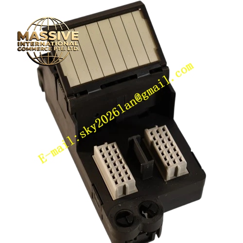
Description
Emerson KJ4001X1-CA1
Technical Specifications
- Compatible hardware: DeltaV series controller modules
- Bus type: DeltaV dedicated high-speed backplane bus
- Redundancy support: Dual controller hot standby mounting
- Operating ambient temperature: 0℃ ~ 60℃
- Storage temperature: -40℃ ~ 85℃
- Relative humidity: 5% ~ 95%, non-condensing
- Vibration resistance: Compliant with IEC 60068-2-6 industrial vibration standard
- Electromagnetic compatibility: Meets IEC 61000 series EMC requirements
Functional Features It delivers power distribution to the controller module through built-in power trace circuits. It maintains stable backplane signal transmission for real-time communication between controller and I/O modules. The carrier provides fixed positioning slots for redundant controller pair, realizing seamless physical layout for hot standby configuration. Integrated signal filtering circuits suppress high-frequency interference from rack power supply. Mechanical locking structure prevents module displacement under continuous cabinet vibration. Status signal routing enables system to detect controller insertion and removal events.
Application Scenarios Main control cabinets of DeltaV distributed control system in petrochemical plants, refineries, thermal power stations and pharmaceutical factories. It works as the base carrier for main and redundant controllers in core process control racks.
Performance Parameters
- Backplane signal transmission maintains low signal attenuation within full operating temperature range
- Power distribution circuit keeps stable voltage supply for controller hardware
- Mechanical structure withstands long-term low-frequency vibration without loose contact
- Redundant slot wiring layout guarantees fast data synchronization between primary and standby controllers
- Continuous 7×24-hour operation without signal interruption
Material Composition The main frame adopts high-strength flame-retardant engineering plastic. The internal backplane uses multi-layer flame-retardant glass fiber epoxy PCB substrate. Gold-plated copper alloy connectors are applied for controller and rack contact terminals. Metal reinforcement brackets improve structural rigidity. Signal traces use impedance-controlled copper lines. Terminal blocks are made of flame-retardant PA plastic with nickel-plated copper wiring terminals.
Structural Features Standard DeltaV rack mounting structure, installed in dedicated controller slots of main rack. Predefined dual positioning slots for primary and redundant controller installation. Built-in guide rails and mechanical latches lock controller modules firmly. Rear gold-plated connector group connects with rack backplane bus. Internal printed circuit traces realize power and signal distribution. Front panel reserved openings for controller status LED observation.
Working Principle The rack backplane supplies DC power to the carrier. Internal power distribution traces transmit regulated power to the controller module. Backplane bus signals pass through the carrier’s impedance-matched signal lines to establish bidirectional communication path between controller and rack I/O modules. When redundant controllers are mounted, the carrier completes hardware signal interconnection for primary-standby data synchronization. The carrier continuously conducts electrical connection monitoring. Any loose contact triggers fault feedback to the DCS system.
Installation Requirements Mount the carrier along the rack guide rail into the designated controller slot and fasten mechanical fixing screws. Ensure the rack protective earth wire connects to cabinet ground bus reliably. Separate control signal cables from high-power motor cables to avoid electromagnetic interference. Reserve sufficient air circulation space above and below the carrier for heat dissipation. Verify all backplane connectors are fully seated before power-on.
Precautions for Use Cut off rack power before carrier installation or replacement. Do not touch gold-plated connector contacts directly by hand to avoid oxidation and contamination. Keep the carrier free of dust accumulation; use dry compressed air for regular cleaning. Do not install non-compatible modules into the carrier slots. Check tightening status of fixing screws periodically to resist equipment vibration. Shut down relevant control loops before removing the carrier from running rack.