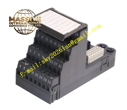
Description
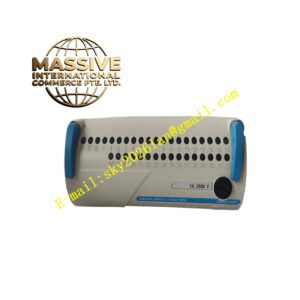
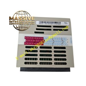
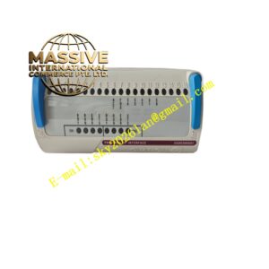
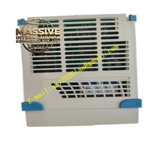
Emerson KJ4001X1‑CJ1
Technical Specifications
- Channel Configuration: multi‑channel mass terminal with per‑channel replaceable miniature fuse holder
- Terminal Connection Type: screw‑clamp terminal, compatible wire gauge 14‑24 AWG
- Fuse Specification: field‑replaceable miniature slow‑blow cartridge fuses
- Maximum Field‑Circuit Voltage: 30 VDC
- Operating Ambient Temperature: ‑40 °C ~ +70 °C
- Storage Temperature: ‑50 °C ~ +85 °C
- Relative Humidity: 5 %‑95 %, non‑condensing
- Airborne Contaminant Grade: ISA‑S71.04‑1985 Class G3
- Protection Class: IP20
- Shock Resistance: 10 g half‑sine pulse for 11 ms
- Vibration Resistance: 1 mm peak‑to‑peak amplitude for 2‑13.2 Hz; 0.7 g acceleration for 13.2‑150 Hz
- Mechanical Feature: rotary anti‑mismatch coding key, integral hot‑swap with matched I/O‑module
- Safety Certification: ATEX, IECEx and FM approval for Zone 2 hazardous‑location deployment
Functional Features Independent per‑channel fuse‑holder structure delivers individual over‑current short‑circuit protection for each field‑signal loop. Field‑replaceable miniature fuses allow on‑site maintenance without disassembling whole terminal‑block assembly. Screw‑clamp terminals complete reliable field‑instrument cable termination. Rotary mechanical coding key prevents mismatched installation of incompatible I/O‑module hardware. Spring‑loaded contact mechanism ensures stable electrical connection under cabinet vibration environment. Obtains bussed field‑power supply from carrier‑base for field‑loop power distribution. Supports integral removal with matched I/O‑module without disconnecting field‑side wiring cables. Surface reserved marking area supports channel‑identification label sticking for on‑site maintenance work. Complies with international hazardous‑area installation certification specifications.
Application Scenarios Petrochemical plants, chemical‑processing facilities and thermal‑power‑plant control cabinets. Mainly applies for discrete output field‑loop wiring which needs independent short‑circuit protection, drives solenoid valves, local indicator lamps and intermediate relay field equipment. When single field‑loop short‑circuit fault appears, fuse cuts off fault channel without affecting operation of other signal loops.
Performance Parameters Fuse protection action characteristic satisfies industrial DC‑loop short‑circuit protection requirement. Terminal‑contact resistance keeps low‑stable status for long‑term service‑life cycle. Mechanical key‑coding mechanism eliminates human‑error hardware mis‑assembly. Electrical connection reliability maintains stable under continuous cabinet vibration condition. Supports 7×24‑hour uninterrupted continuous industrial‑site running.
Material Composition Flame‑retardant high‑strength engineering‑plastic housing, integrated fuse‑compartment structure. Tin‑plated copper‑alloy screw‑clamp terminal contact parts and fuse‑clip components. Glass‑epoxy printed‑circuit substrate for internal signal and power trace routing. Stainless‑steel mechanical locking hardware for fastening onto M‑Series carrier‑base.
Structural Characteristics Modular snap‑on construction for front‑face installation onto M‑Series I/O carrier‑base. Front‑plane integrates screw‑clamp terminal rows and independent accessible fuse‑holder compartments. Rotary coding dial located on side wall for hardware‑compatibility setting. Rear‑side contact assembly precisely mates with front‑side contact points of M‑Series I/O‑module. Side‑mounted locking latches fasten terminal‑block unit firmly onto carrier‑base front plane. Blank marking zone reserved on housing surface for signal‑channel identification tagging.
Working Principle Field‑instrument cables terminate onto KJ4001X1‑CJ1 front‑side screw‑clamp terminals. Field‑loop current passes through channel‑specific miniature fuse component inside terminal‑block internal circuit. Under normal working status, fuse keeps conducting state, field‑signal transmits through internal traces and rear‑side contact assembly into corresponding channel circuit of plugged‑in M‑Series I/O‑module. When short‑circuit or severe over‑current fault occurs on individual field‑loop, corresponding fuse element fuses, cuts off fault‑loop power supply and isolates fault influence to other channels. Bussed field‑power supply from carrier‑base distributes to each channel through fuse‑holder components. Rotary mechanical coding dial defines compatible I/O‑module hardware type and blocks mismatched hardware combination. This terminal‑block is passive wiring‑protection hardware without built‑in signal‑processing chip.