Description
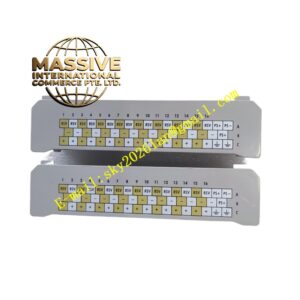
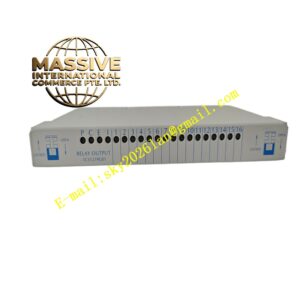
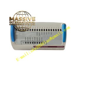
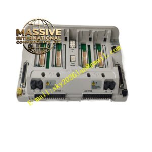
Emerson L ID43.03
Technical Specifications
- Input signal: Eddy current probe signal, acceleration sensor analog signal
- Operating ambient temperature: 0℃ ~ 60℃
- Storage temperature: -40℃ ~ 85℃
- Relative humidity: 5% ~ 95%, non-condensing
- Built-in signal amplification, filtering and high-speed sampling circuit
- Support waveform capture for transient vibration events
- Alarm relay output interface
Functional Features High-performance analog front-end circuit amplifies weak sensor signals and filters out high-frequency industrial noise. High-speed ADC converts analog vibration waveform into digital data for onboard calculation. Independent warning and trip threshold configuration for each measuring channel. Relay contact output triggers external interlock protection when measured value exceeds threshold. Onboard memory stores waveform data during fault events for post-fault analysis. Front panel LED indicators display channel status, warning and trip events.
Application Scenarios Machinery protection racks for steam turbines, centrifugal compressors, large fans and heavy-duty motors in power plants, oil refineries and chemical processing plants.
Performance Parameters
- High sampling rate captures transient vibration peak signals of rotating equipment
- Analog filtering circuit maintains stable measurement under complex industrial electromagnetic noise
- Threshold comparison circuit responds quickly once vibration value exceeds limit
- Relay contacts achieve stable switching action for protection interlock circuits
- Measurement accuracy keeps consistent during long-term continuous operation
Material Composition Metal shielding housing with anti-static coating. Multi-layer flame-retardant glass fiber epoxy PCB. Analog signal conditioning chips, high-speed ADC, digital processing microprocessor, relay components and LED indicators. Gold-plated connectors for sensor wiring and rack backplane connection. Terminal blocks use flame-retardant PA plastic and nickel-plated copper terminals.
Structural Features Standard rack plug-in module for machinery monitoring chassis. Front panel equipped with LED indicators for channel status and alarms. Internal metal shielding layer reduces electromagnetic interference. Rear connector group connects rack backplane and field sensor cables. Mechanical latches lock module inside rack guide rail.
Working Principle Vibration and displacement sensors installed on rotating equipment send raw analog signals to module input channels. Front-end circuit amplifies and filters raw signals. High-speed analog-to-digital converter converts analog waveform into digital data. Onboard processor calculates vibration amplitude, shaft displacement and rotational speed. Measured values are compared with preset warning and trip thresholds. When values exceed thresholds, relay contacts switch state and send alarm signals to host monitoring system. The module captures and stores vibration waveform data for fault diagnosis.
Installation Requirements Insert module into designated slot of machinery monitoring rack and lock fasteners. Separate sensor cables from high-power cables to reduce electromagnetic interference. Use dedicated low-noise coaxial cables for eddy current probes. Ensure cabinet protective earth connects reliably to ground bus. Complete probe gap calibration and threshold parameter configuration after hardware installation.
Precautions for Use Cut off sensor loop power before connecting probe cables. Do not bend eddy current probe coaxial cable with small bending radius. Verify probe gap calibration after installation. Do not apply high voltage to sensor input terminals. Backup configuration parameters before module replacement. Inspect cable insulation and connector condition regularly.