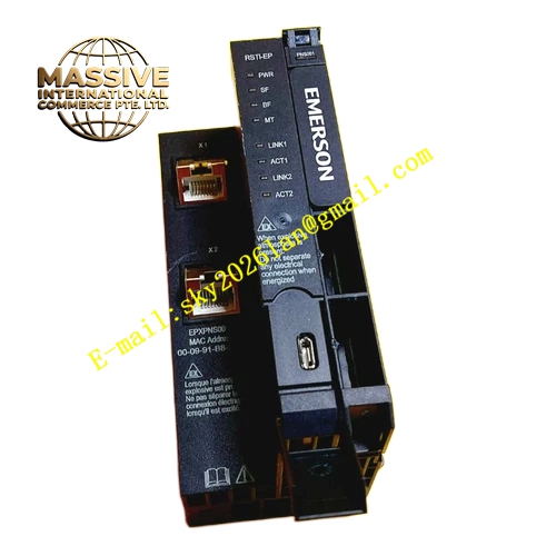
Description
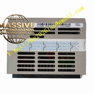
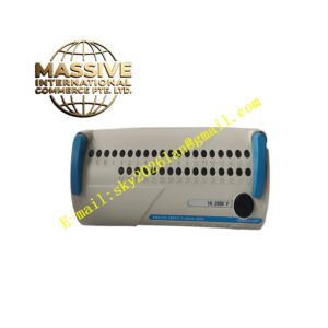
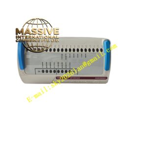
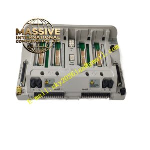
Emerson PMC-IO-ADAPTER
Technical Specifications
- Operating temperature range: 0°C to 60°C
- Storage temperature range: -40°C to 85°C
- Ambient humidity: 5% to 95% non-condensing
- Bus signal rate matches PMC controller internal communication
- Supports hot swap within compatible rack assemblies
- Provides electrical isolation between controller side and I/O backplane side
Functional Features Transmits bidirectional data signals between PMC controller and rack I/O modules. Performs signal level conversion for different bus interfaces. Built-in hardware isolation blocks ground loop interference between controller and I/O sections. Onboard diagnostic circuits monitor communication link health continuously. Front panel LED indicators display link status and fault alarms. Supports redundant system architecture for critical process control applications.
Application Scenarios Installed inside Emerson DCS control cabinets for process industries including petrochemical, power generation, pulp and paper, and water treatment. Used to connect PMC series controllers with analog and digital I/O racks to complete field signal acquisition and control output tasks.
Performance Parameters
- Stable high-speed bidirectional data transmission
- Low signal attenuation across the interface
- High immunity against industrial electromagnetic noise
- Continuous 24-hour operation without signal dropout
Material Composition Main circuit board uses flame-retardant glass fiber epoxy PCB substrate. Signal conversion and isolation chips are soldered onto the PCB. Metal shielding layer suppresses external electromagnetic interference. Backplane connectors adopt gold-plated contact pins to deliver low contact resistance and oxidation resistance. Structural frame uses high-strength flame-retardant plastic.
Structural Characteristics Standard rack plug-in card form factor matching designated rack slots. Front panel carries status LED indicators. Mechanical locking buckle prevents module loosening induced by cabinet vibration. Internal circuit layout separates controller bus circuits and I/O bus circuits to reduce crosstalk. Compact dimension saves cabinet installation space.
Working Principle The PMC controller sends control commands and reads field data through the adapter module. The adapter receives digital bus signals from the controller, converts signal levels and protocol framing, then transmits processed signals to the rack backplane for I/O modules. Signals returned from I/O modules go through reverse conversion before being delivered back to the PMC controller. The onboard diagnostic circuit checks communication quality in real time and reports link faults to the control system.
Installation Requirements Insert the adapter module into the dedicated slot of the matched control rack and fasten the locking buckle. Ensure the backplane connector fully seats into the rack backplane. Keep ventilation channels unobstructed around the module. Maintain reliable protective grounding of the cabinet. Separate signal cables from high-voltage power cables during cabinet wiring.
Use Precautions Cut off rack power supply before removing the adapter module in non-redundant systems. Do not apply physical impact to the circuit board during handling. Prevent metal debris from falling onto the connector pins. Replace the module immediately if persistent communication failure occurs after cable inspection.