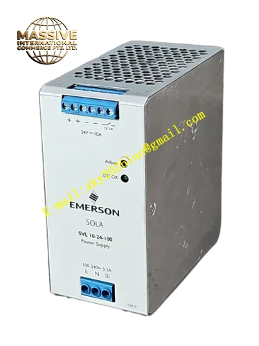
Description
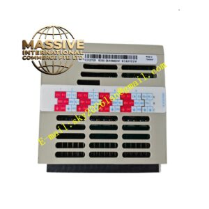
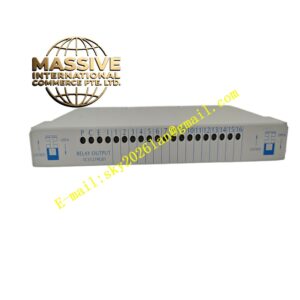
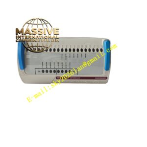
Emerson PSM-E10
Technical Specifications: Power supply: 24 VDC Number of monitoring channels: up to 10 power sampling channels Relay contact rating: 250 VAC, 3 A Operating temperature: 0 ℃ to 60 ℃ Storage temperature: -40 ℃ to 85 ℃ Relative humidity: 5% to 95% non-condensing Communication interface: RS485
Functional Features: Multi-channel power parameter synchronous monitoring. Record fault event and store fault history. Multiple groups of relay dry contact alarm output. Hardware overvoltage, undervoltage, overcurrent and overtemperature judgment. LED indicators display each channel status. Digital communication upload real-time power data. Supports remote parameter configuration.
Application Scenarios: Large DCS main control rack power monitoring, power plant machinery protection system power monitoring, petrochemical main control cabinet redundant power monitoring, metallurgy automation cabinet power condition monitoring, large paper mill control rack power monitoring.
Performance Parameters: Voltage measurement accuracy: ±0.5% full scale Vibration resistance: 10 Hz to 150 Hz, 0.5 g Shock resistance: 10 g peak acceleration, 11 ms duration MTBF value: 218000 hours
Material Composition: Module housing: UL94-V0 flame-retardant metal shell. Main PCB: FR-4 glass fiber epoxy printed board. Backplane connector pins: gold-plated copper alloy. Terminal blocks: nickel-plated brass. Side locking latches: reinforced engineering plastic.
Structural Features: Standard rack plug-in module. Two side locking latches fix module to rack backplane. Front panel equipped with multi-channel LED indicators and signal terminals. Rear multi-pin gold-plated connector connects rack backplane power and bus. Internal metal shielding suppresses electromagnetic interference. Ventilation slots on shell for heat dissipation.
Working Principle: The module collects voltage, current and temperature sampling signals from each power module. Internal processor calculates power parameters and compares data with preset alarm thresholds. When any power channel exceeds limit, corresponding relay contact activates and records fault information. Real-time power data and fault history transmit to upper monitoring system through RS485 bus.
Installation Requirements: Insert module into designated slot of large control rack and lock latches. Route sampling signal cable separately from high-power power cable. Use shielded twisted pair cable for communication wiring. Cut off rack power before installing or removing module. Complete threshold configuration after power on.
Precautions for Use: Do not exceed rated relay contact load. Wear anti-static wristband during maintenance. Check sampling wiring connection periodically. Keep ventilation slots free of dust accumulation. Do not install in environment with corrosive gas.