Description
Emerson SE4005S2B1
Technical Specifications: Operating voltage: 24 VDC Load voltage: 24 VDC field side Per-channel current: 500 mA maximum Isolation: 500 VAC between field and system Operating temperature: 0 ℃ to 60 ℃ Storage temperature: -40 ℃ to 85 ℃ Relative humidity: 5% to 95% non-condensing Mounting: 35 mm DIN rail
Functional Features: Field wiring terminals for digital output loads. Per-channel electronic fuse and over-current protection. Surge suppression for inductive load switching. Hot-swap of electronic output module. Channel status test points. Electronic identification for I/O type recognition. Flyback diode for inductive load suppression.
Application Scenarios: Solenoid valve control in chemical plant, pump start-stop relay output, alarm lamp drive control, packaging machine actuator control, conveyor belt motor interlock output.
Performance Parameters: Channel response time: less than 1 ms Per-channel maximum load: 500 mA Terminal contact resistance: less than 10 mΩ Mounting: standard 35 mm DIN rail
Material Composition: Housing: UL94-V0 flame-retardant thermoplastic. PCB: FR-4 glass fiber epoxy. Terminal screws: nickel-plated brass. Backplane connector: gold-plated copper alloy. DIN rail clip: stainless steel.
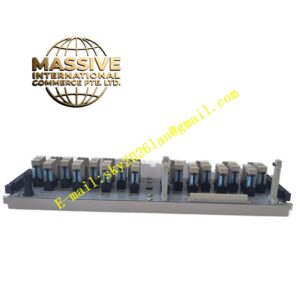
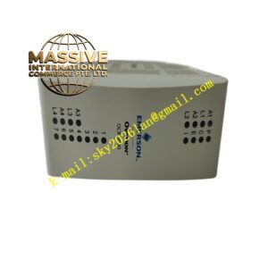
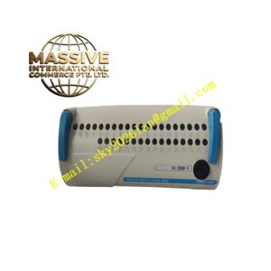
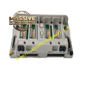
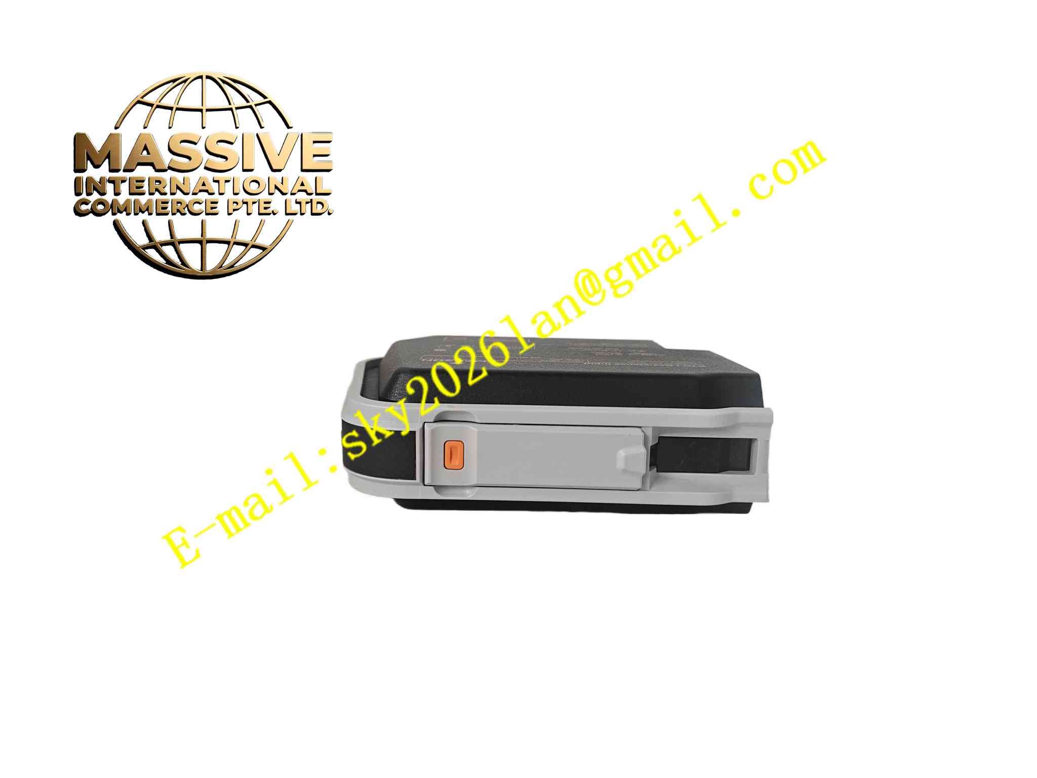
Structural Features: DIN rail snap-mount terminal block. Front terminal rows for field load wiring. Top slot for digital output electronic module. Label strip on front for channel identification. Test points per channel.
Working Principle: Field load wires connect to front terminals. Digital output module sends switching commands through internal connector. Terminal block drives load circuit with per-channel protection. Flyback diodes suppress inductive load voltage spikes. Electronic identification chip signals output channel type to DeltaV system. Fault current on any channel trips independent protection circuit.
Installation Requirements: Mount on 35 mm DIN rail. Route load cables away from analog signal cables. Tighten terminals to 0.5 N·m. Connect freewheeling diode for inductive loads. Ensure cabinet protective ground is complete.
Precautions for Use: Do not exceed 500 mA per channel. Do not connect AC load to DC output terminals. Wear anti-static wristband when swapping output module. Keep terminal block free of conductive debris. Inspect load wiring for short circuits before energizing.