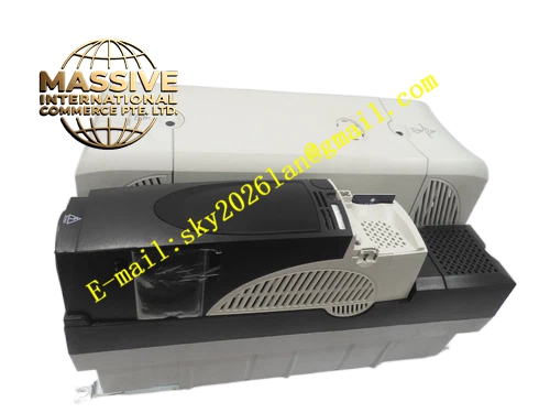
Description
Emerson SP6401‑HF
Technical Specifications
- Input Power: Three‑phase AC
- Control Mode: Open‑loop vector control, closed‑loop vector control
- High‑frequency output function for high‑speed motor
- Overload Capacity: 150% rated current for 60 seconds
- Operating Ambient Temperature: 0℃ ~ 40℃
- Storage Temperature: -40℃ ~ 70℃
- Relative Humidity: 5% ~ 95%, non‑condensing
- Protection Grade: IP20 for cabinet installation
- Built‑in overcurrent, overvoltage, undervoltage, overtemperature and motor overload protection
Functional Features High‑speed digital processor executes vector control algorithm for high‑frequency motor speed regulation.
High‑frequency IGBT power module converts DC bus power into high‑frequency three‑phase AC output for high‑speed motor.
Multiple hardware protection circuits continuously monitor drive and motor operating state.
Built‑in programmable logic supports simple local logic control.
Front panel keypad and display unit support local parameter setting and fault code query.
Supports multiple industrial communication buses to connect with upper PLC or motion controller.
Forced air cooling design guarantees stable heat dissipation under continuous high‑frequency operation.
Application Scenarios High‑speed machine tool spindle, high‑speed grinding machine, high‑speed centrifugal equipment and special high‑speed processing automation equipment.
It supplies high‑frequency variable frequency power to high‑speed AC motors and realizes high‑speed rotation adjustment.
Performance Parameters Vector control algorithm maintains stable speed accuracy under high‑frequency operation condition.
High‑frequency power module outputs stable variable frequency three‑phase power.
Protection circuit triggers protection action immediately once abnormal electrical parameters appear.
Communication interface maintains reliable data transmission with upper control system.
Drive runs stably for long time under rated ambient temperature and load condition.
Material Composition Flame‑retardant plastic front panel with keypad and digital display.
Metal base and large metal heat sink.
Multi‑layer glass‑fiber epoxy printed circuit board for control circuit.
High‑frequency IGBT power semiconductor modules, sampling resistors and capacitors.
Cooling fan assembly.
Structural Features Vertical cabinet mounting structure for installation inside electrical control cabinet.
Front panel equipped with operation keypad and digital display screen.
Rear large metal heat sink for power module heat dissipation.
Cooling fan for forced air cooling.
Terminal area at bottom for power cable and control signal cable wiring.
Internal isolation barrier separates high‑power main circuit and low‑voltage control circuit.
Working Principle Three‑phase AC mains power enters drive main circuit through power terminals.
Rectifier circuit converts alternating current into direct current stored in DC bus capacitors.
High‑frequency IGBT inverter module converts DC power into high‑frequency variable frequency and variable voltage three‑phase AC power according to control instruction.
High‑frequency AC power outputs to high‑speed motor to adjust motor rotating speed.
Control processor collects motor current and voltage signals continuously, executes vector control algorithm and adjusts inverter output state in real time.
Protection circuit monitors current, voltage and internal temperature of drive. When abnormal condition occurs, drive stops output and triggers fault alarm.
Installation Requirements Mount drive vertically on rigid mounting plate inside control cabinet.
Reserve sufficient air gap at upper and lower side for cooling air circulation.
Separate main power cables and low‑voltage control signal cables, use shielded cable for encoder and communication wiring.
Install input circuit breaker and AC reactor according to power specification.
Complete motor parameter self‑tuning and high‑frequency control parameter configuration after hardware installation.
Precautions for Use Cut off main power supply and wait for DC bus capacitor discharge before opening drive cover.
Do not block air inlet and air outlet of cooling fan.
Check fan running state and heat sink dust accumulation during regular maintenance.
Do not connect motor load exceeding drive rated capacity.
Do not disassemble power module and internal control circuit.
Do you want to continue processing next batch of part numbers with this format?