Description
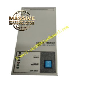
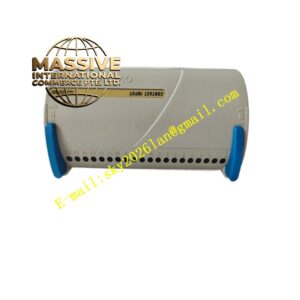
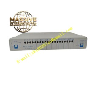
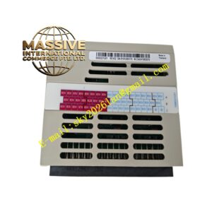
Emerson SP9435
Technical Specifications
- Input Voltage Range: 85VAC ~ 264VAC
- Multi‑channel DC output for I/O modules
- Redundant hot backup parallel support
- Built‑in overvoltage, undervoltage, overcurrent and overtemperature protection
- Operating Ambient Temperature: 0℃ ~ 60℃
- Storage Temperature: -40℃ ~ 85℃
- Relative Humidity: 5% ~ 95%, non‑condensing
- Rack plug‑in installation
- LED indicators for power status and fault
Functional Features
Wide AC input range adapts to industrial grid fluctuation at field workshop. Multiple DC outputs supply power for digital I/O, analog I/O modules and terminal bases separately. Redundant parallel design ensures continuous power supply of I/O rack when single power module fails. Hardware protection circuit cuts off output rapidly under fault conditions. Front panel LED indicators show running state and fault information. Plug‑in mechanical structure supports hot swap under non‑critical process conditions.
Application Scenarios
Ovation remote I/O racks deployed in thermal power plants, chemical factories, pulp and paper mills. It supplies power for all I/O modules inside distributed field I/O cabinets.
Performance Parameters
Power conversion circuit maintains stable DC output under full I/O rack load within rated temperature range. Redundant switchover completes instantly without interruption of I/O signal collection and output. Protection circuit responds quickly once parameters exceed safety threshold. Low ripple output reduces interference to analog I/O signal acquisition.
Material Composition
Metal housing with anti‑corrosion coating. Multi‑layer flame‑retardant glass fiber epoxy PCB. High‑frequency transformer, rectifier diodes, filter capacitors, power switching tubes and sampling chips. Gold plated copper alloy backplane connector. Flame‑retardant plastic front panel with LED indicators.
Structural Features
Standard plug‑in module for Ovation I/O rack power slot. Front panel equipped with power running LED and fault alarm LED. Internal metal shielding reduces electromagnetic radiation. Rear gold plated connector mates with I/O rack backplane. Air inlet and outlet vents on housing for heat dissipation.
Working Principle
AC power enters module through rack backplane connector. AC‑DC conversion circuit converts alternating current into stable direct current after rectification, filtering and voltage regulation. DC power transmits to each I/O module slot through I/O rack backplane. Sampling circuit continuously monitors output voltage, current and internal temperature. When parameters exceed preset limit, hardware protection circuit activates and triggers fault alarm signal. Two redundant modules share load in normal working state, and healthy module undertakes full load when the other module fails.
Installation Requirements
Cut off rack AC power before installation. Insert module along rack guide rail into power slot and lock mechanical latch. Confirm AC wiring meets power specification. Ensure air inlet and outlet vents stay unblocked. Configure redundant power function on DCS engineering station when two power modules are installed.
Precautions for Use
Apply anti‑static protection during module handling. Do not block cooling vents on module housing. Inspect AC input cable tightness regularly. Do not disassemble metal housing of power module. Replace module immediately once fault alarm lights up.