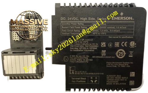
Description
Emerson VE4003S2B10
Technical Specifications
- Number of output channels: 8 safety digital output channels
- Output type: 24VDC safety output
- Safety certification: SIL2 certified
- Operating ambient temperature: 0℃ ~ 60℃
- Storage temperature: -40℃ ~ 85℃
- Relative humidity: 5% ~ 95%, non-condensing
- Built-in channel diagnostic circuit for wire break and short circuit detection
- Backplane interface: DeltaV SIS dedicated safety bus
- Support hot swap under permitted safety conditions
Functional Features Each channel carries out continuous hardware diagnostics to detect short circuit, open circuit and internal component failure. Dual redundant output circuit design improves reliability for safety interlock actions. Optical isolation separates SIS backplane circuit and field actuator wiring to block surge and common-mode interference. Front panel LED indicators display individual channel working status and fault alarms. The module executes command output from SIS logic solver and sends feedback of channel health status to the safety controller.
Application Scenarios Safety instrumented cabinets in petrochemical plants, refineries and chemical factories. It controls emergency shutdown solenoid valves, fire suppression valves and safety trip relays in ESD and FGS protection systems.
Performance Parameters
- Channel diagnostic circuit achieves high diagnostic coverage of hardware faults
- Output drive circuit maintains stable 24VDC output under rated load
- Optical isolation withstands high common-mode voltage from field wiring
- Safety bus communication guarantees integrity of safety command transmission
- Response speed satisfies the required reaction time of safety interlock loops
Material Composition Flame-retardant engineering plastic housing. Multi-layer flame-retardant glass fiber epoxy PCB substrate. Safety processing microcontroller, optical isolation chips, output drive transistors, diagnostic sampling circuits and LED indicators. Gold-plated copper alloy backplane connector. Matching terminal base adopts flame-retardant PA plastic and nickel-plated copper screw terminals.
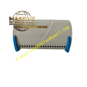
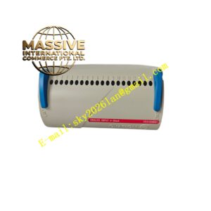
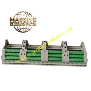
Structural Features Standard plug-in card structure for DeltaV SIS rack slots. Front panel equipped with module fault indicator and independent LED lights for each of 8 channels. Guide rails and mechanical latches lock the module firmly inside rack to resist industrial vibration. Rear gold-plated connector mates with SIS safety backplane bus. Front terminal base accepts field actuator wiring cables.
Working Principle Safety commands transmitted from SIS logic solver arrive at the module via safety backplane bus. The onboard safety processor verifies command integrity and activates corresponding output channel. The drive circuit sends 24VDC power to field safety actuators. Sampling circuits continuously monitor output loop current and voltage to identify wire break or short circuit. Once hardware or wiring fault is detected, the module triggers fault alarm and uploads fault information to SIS logic solver.
Installation Requirements Insert the module along rack guide rail into designated SIS rack slot and lock mechanical latch. Use shielded twisted pair cables for field actuator wiring. Cable shield connects to cabinet ground at single end only. Separate safety signal cables from non-safety power cables. Keep sufficient air circulation space above and below the module for heat dissipation. Complete safety loop proof test after installation.
Precautions for Use Cut off field actuator power before wiring work. Do not mix safety wiring with ordinary control cables. Verify safety function after module replacement. Never disable built-in channel diagnostic functions. Execute periodic proof tests according to site safety operation procedures. Do not disassemble module housing.