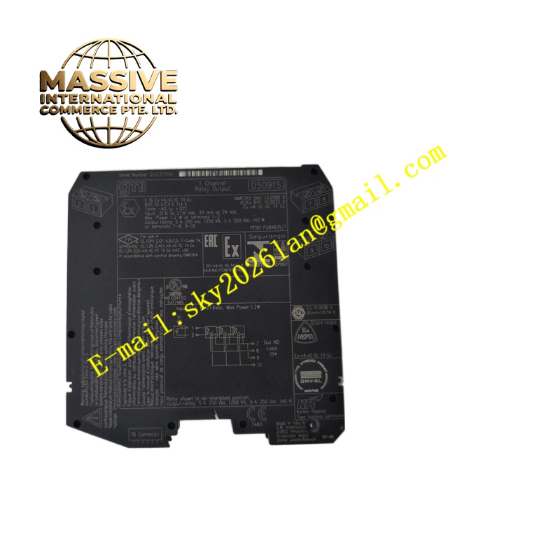
Description
Technical Specifications Safety integrity level SIL 3; power supply 24 V DC; typical power consumption 1.1 W; input/output galvanic isolation rating 2.5 kV; single SPDT relay contact; rated contact load 5 A at 250 V AC or 24 V DC; operating temperature range -40 ℃ to +70 ℃; storage temperature -45 ℃ to +80 ℃; weight 125 g; installation suitable for Zone 2 / Division 2 hazardous areas; PFDavg and SFF parameters meet SIL 3 safety calculation requirements.
Functional Features Two configurable safety function modes selected by DIP switches; line monitoring function detects wire break or short circuit on input wiring; dedicated safety contact and non-safety auxiliary service contact on separate terminal groups; built-in self-test verifies relay circuit health; fault status indication through front panel LED; certified for use in functional safety instrumented systems.
Application Scenarios Oil and gas pipeline safety shutdown circuits, chemical plant emergency valve control, power plant burner trip logic, pharmaceutical explosion-risk zone safety interlock, refinery safety instrumented systems.
Material Composition Flame-retardant self-extinguishing plastic DIN rail housing; internal PCB is FR4 printed circuit board with safety-rated components; relay contact material uses silver alloy with anti-wear coating; screw terminal blocks accept stranded and solid copper conductors; front panel translucent plastic window covers diagnostic LED indicators.
Structural Characteristics Compact vertical DIN rail enclosure; front panel carries power, fault and status LED indicators; upper and lower screw terminal blocks separate input signal terminals and load output terminals; DIP switch bank accessible on front panel for mode configuration; internal isolation barrier separates low-voltage input circuits and power output contact circuits.
Working Principle 24 V DC safety logic input signal controls internal safety relay coil. DIP switch configuration defines whether de-energisation or energisation triggers safe state. Input line monitoring circuit continuously checks input wiring integrity. If wiring fault or safety trip command occurs, relay contact transfers to predefined safe state. Auxiliary contact provides independent non-safety status feedback signal.
Installation Requirements Clip module onto standard 35 mm DIN rail inside safe-area control cabinet; torque terminal screws to datasheet specified value; separate safety circuit wiring from non-safety control cables; configure DIP switch setting before applying power supply; verify safety loop calculation and SIL verification report before commissioning.
Operation Notes Do not modify internal circuit components; execute proof test according to safety manual scheduled interval; replace module immediately after safety fault diagnosed; do not use auxiliary service contact for safety instrumented functions.