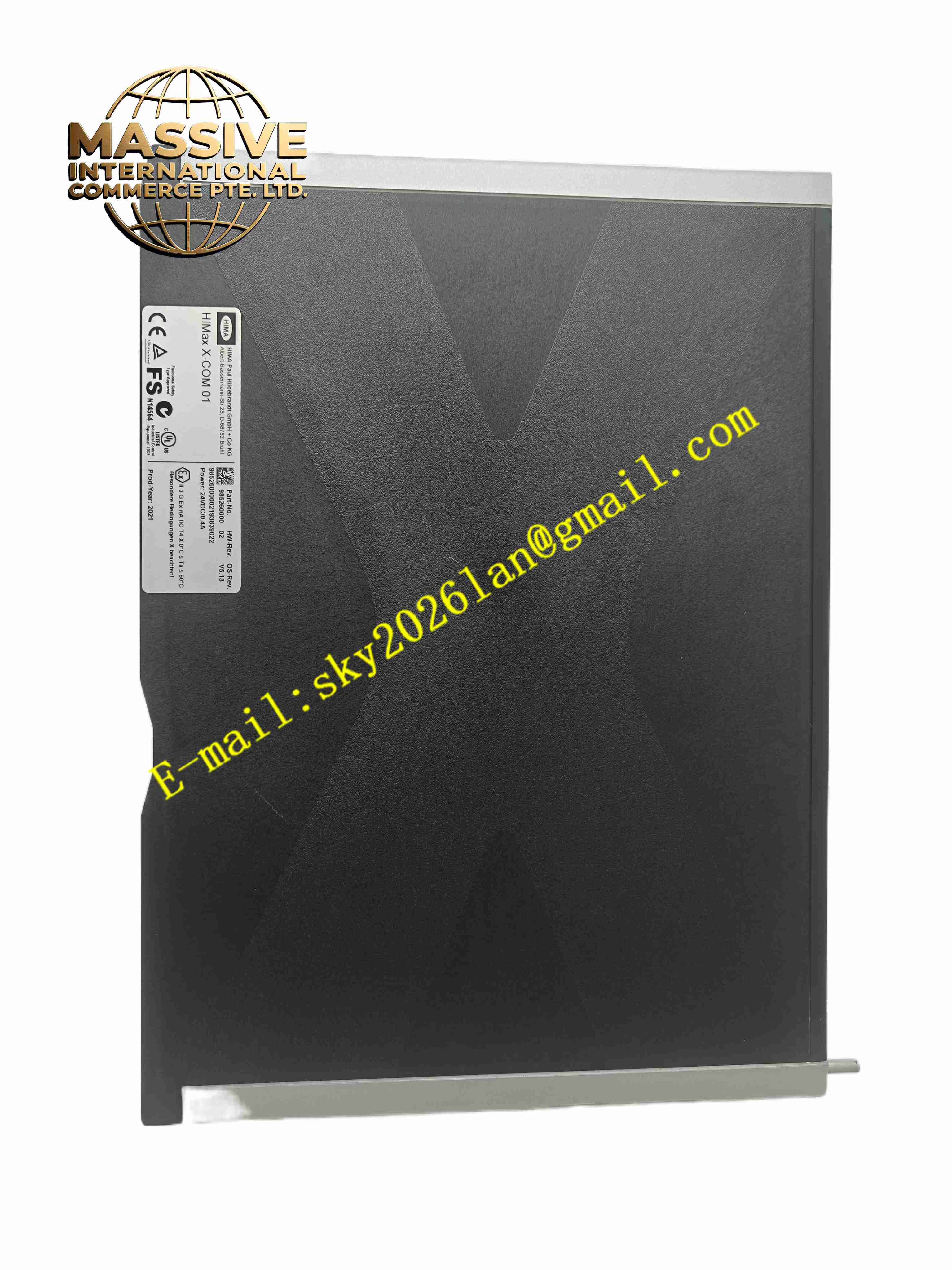
Description
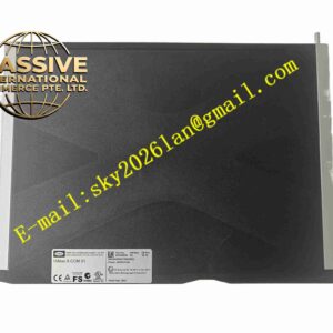
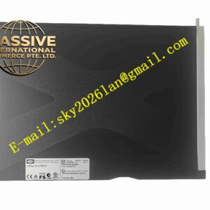
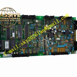
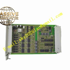
HIAM X-DI3201
Technical Specifications:
- Channel Quantity: 32 digital input channels
- Input Type: Dry contact / 24VDC wet contact input
- Isolation: Each channel group with galvanic isolation
- Power Supply: 24VDC
- Response Time: <1ms per channel
- Operating Temperature: -20℃ ~ +65℃
- Storage Temperature: -40℃ ~ +85℃
- Humidity: 5%~95% non-condensing
Function Features:
- 32 channels digital switch signal acquisition
- Galvanic isolation for each signal group to avoid interference
- Signal filtering to suppress contact bounce and noise
- Real-time uploading of switch status to main controller
- Channel fault diagnosis function
- Overvoltage and surge protection for input terminals
Application Scenarios:
- Power plant excitation control cabinet signal collection
- Generator protection and monitoring systems
- Industrial DCS and PLC control systems
- Substation automation control equipment
Material Composition:
- Housing: Flame retardant plastic or metal DIN rail housing
- PCB: FR4 fiberglass circuit board
- Core Components: Optocoupler isolation chips, digital logic chips, surge protection devices
- Terminals: Screw type copper alloy terminals
Structural Features:
- DIN rail mounting module
- LED status indicator for each channel
- Separate terminal blocks for field input signals and module power supply
- Compact modular design for cabinet expansion
Working Principle: Field switch contact signals enter module input terminals. Optical couplers realize electrical isolation between field side and internal logic circuit. Input signals are filtered and converted into digital logic signals. The module scans all channels continuously and sends switch status data to the main control system via internal bus.
Installation Requirements:
- Mount on standard DIN rail inside control cabinet
- Separate field signal wiring from high-voltage power cables
- Use twisted pair cable for field switch signal wiring
- Supply 24VDC power within rated voltage range
- Ensure cabinet ventilation to avoid overheating
Usage Notes:
- Check input signal type (dry or wet contact) before wiring
- Do not connect voltage exceeding rated input range to channels
- Prevent dust and moisture entering module housing
- Check terminal screw tightness periodically
- Disconnect power before wiring modification