Description
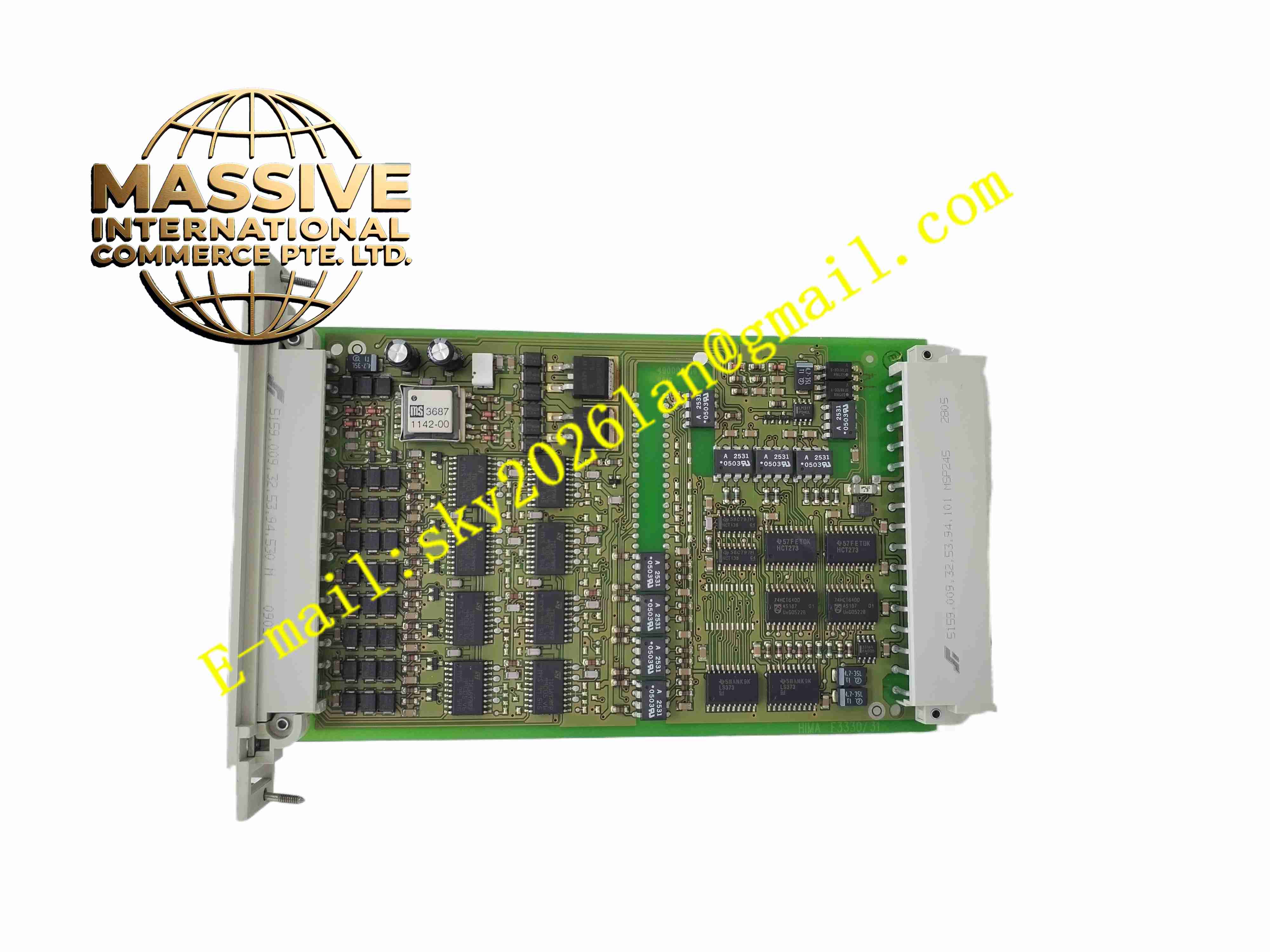
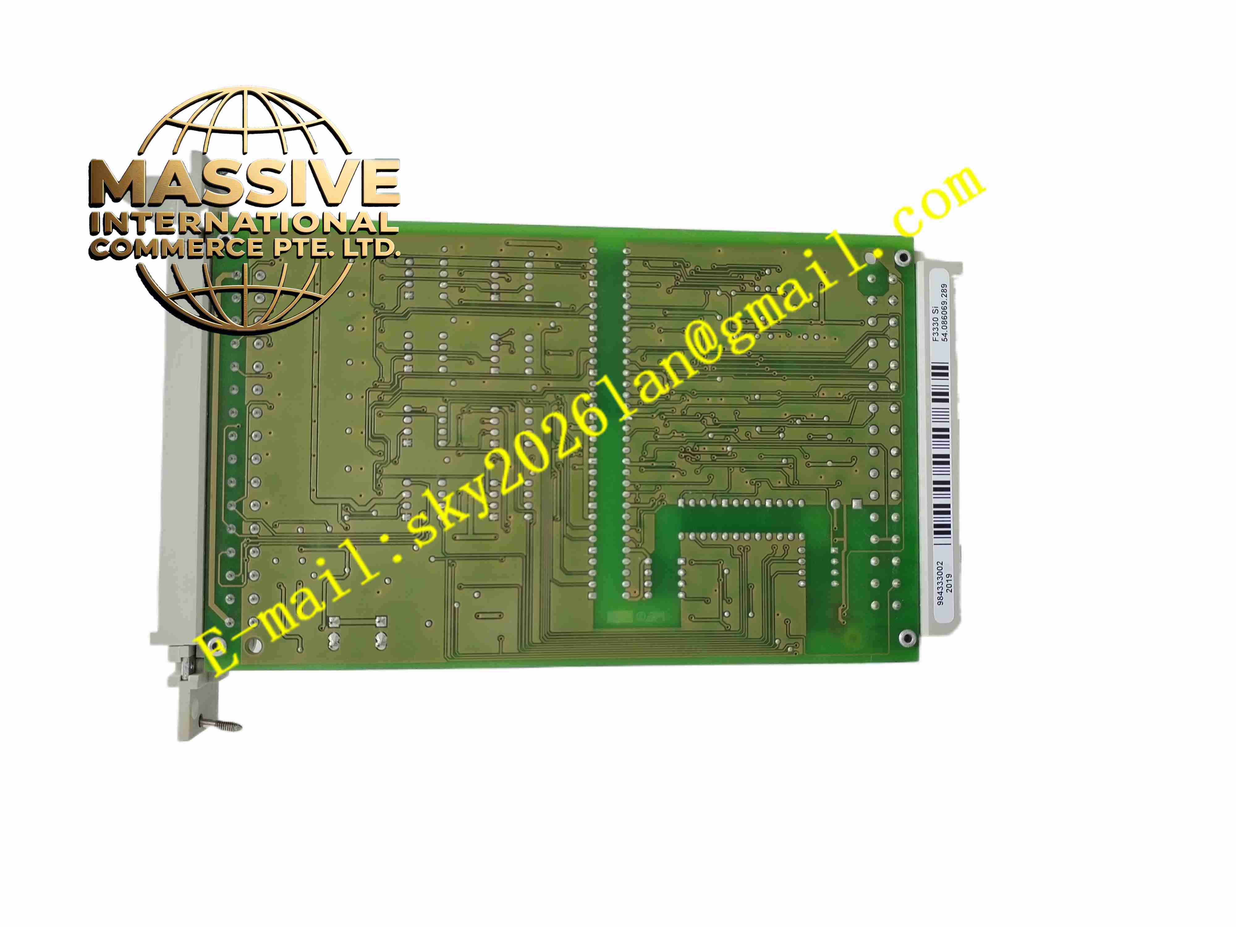
HIMA F3330 (984333002)
Technical Specifications
Brand: HIMA
Model: F3330
Part number: 984333002
Module type: 8-fold safety-related digital output module
Output channels: 8
Load capacity, resistive/inductive: 500 mA per channel, 12 W
Load capacity, lamp: 4 W maximum, up to 10 W with external resistor
Supply voltage: 5 V DC at approximately 110 mA; 24 V DC at approximately 180 mA plus load current
Short-circuit current operating point: 0.75 A to 1.5 A
Output leakage current: Maximum 350 µA
Internal voltage drop: Maximum 2 V at 500 mA load
Undervoltage tripping: Approximately 16 V at 500 mA load
Admissible line resistance: Maximum 11 Ohm, input and output combined
Reset voltage: Maximum 1.5 V
Zero-signal operating point: 6.5 V or less
Space requirement: 4 TE
Weight: Approximately 0.25 kg
Certifications: TÜV, CE
Functional Features
Eight independent safety-related output channels
Support for resistive and inductive loads up to 500 mA
Support for lamp loads up to 4 W
Extended lamp load capability up to 10 W with external resistor
Integrated safety shutdown function
Safe isolation compliant with AK 1 to AK 6 classes
Automatic in-operation testing
Output signal readback monitoring
Walking-bit test for cross-talk detection
Short-circuit proof output design
Low output leakage current to prevent false triggering
Undervoltage tripping for safe operation
No output signal when L- supply is interrupted
Compatible with inductive loads when protected by suitable diodes
Application Scenarios
Emergency shutdown actuator control
Safety relay and contactor tripping
Solenoid valve isolation control
Fire and gas system output signaling
Burner management system shutdown outputs
Turbine and compressor protection outputs
Pipeline safety valve control
Process interlock actuation
Industrial machinery safety circuits
Safety alarm and indication outputs
Performance Parameters
Channel count: 8 digital outputs
Maximum continuous load current: 500 mA per channel for resistive/inductive loads
Maximum lamp load: 4 W without external resistor
Maximum lamp load with external resistor: 10 W
Internal voltage drop: Maximum 2 V at 500 mA
Output leakage current: Maximum 350 µA
Short-circuit current range: 0.75 A to 1.5 A
Line resistance limit: 11 Ohm maximum
Undervoltage trip level: Approximately 16 V
Power supply requirement: 5 V DC and 24 V DC
Module width: 4 TE
Weight: Approximately 0.25 kg
Material Composition
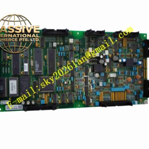
Industrial printed circuit board
Safety-rated output driver circuitry
Short-circuit protection components
Isolation barriers for safe signal separation
Power regulation circuitry for 5 V DC and 24 V DC operation
Diagnostic and monitoring electronics
Status LED indicators
Module housing and connector interface
Structural Features
Compact 4 TE module width
Eight output channels in a single module
Front or top status indicators for channel and fault monitoring
Backplane or system bus interface for HIMA safety controllers
Removable or fixed wiring interface depending on system frame
Clear module labeling with F3330 and 984333002
Designed for installation in HIMA safety racks
Robust industrial construction for control cabinet environments
Working Principle
The F3330 receives output commands from the HIMA safety controller and switches each of its eight channels to energize or de-energize connected field devices. During operation, the module continuously monitors output status through readback circuits and performs automatic self-tests to verify switching capability and detect cross-talk. If a short circuit, open circuit, undervoltage condition, or internal fault is detected, the module initiates a safe shutdown of the affected outputs. When the L- supply is interrupted, the module prevents unintended load activation. This behavior ensures that field devices enter or remain in a safe state when a fault occurs.
Installation Requirements
Install the module in a compatible HIMA safety rack
Verify that the part number 984333002 matches the required replacement
Connect field wiring according to HIMA installation guidelines
Ensure that load current does not exceed 500 mA per channel for resistive/inductive loads
Use external resistors when lamp loads exceed 4 W
Protect inductive loads with appropriate free-wheeling diodes such as 1N4007 or 1N4448
Verify 5 V DC and 24 V DC supply voltages before commissioning
Check cable resistance to remain within the 11 Ohm maximum limit
Configure and test the module using authorized HIMA engineering software
Maintain proper cabinet grounding and electromagnetic compatibility practices
Usage Precautions
Do not exceed the rated load current or power limits
Do not use the module for non-safety applications without system validation
Verify lamp load ratings before connecting lighting circuits
Replace faulty modules only with genuine HIMA parts
Keep firmware and safety application configuration under change control
Monitor diagnostic messages and relay output status regularly
Avoid modifying field wiring while the safety system is energized
Refer to the official HIMA F3330 documentation for exact wiring, testing, and certification details