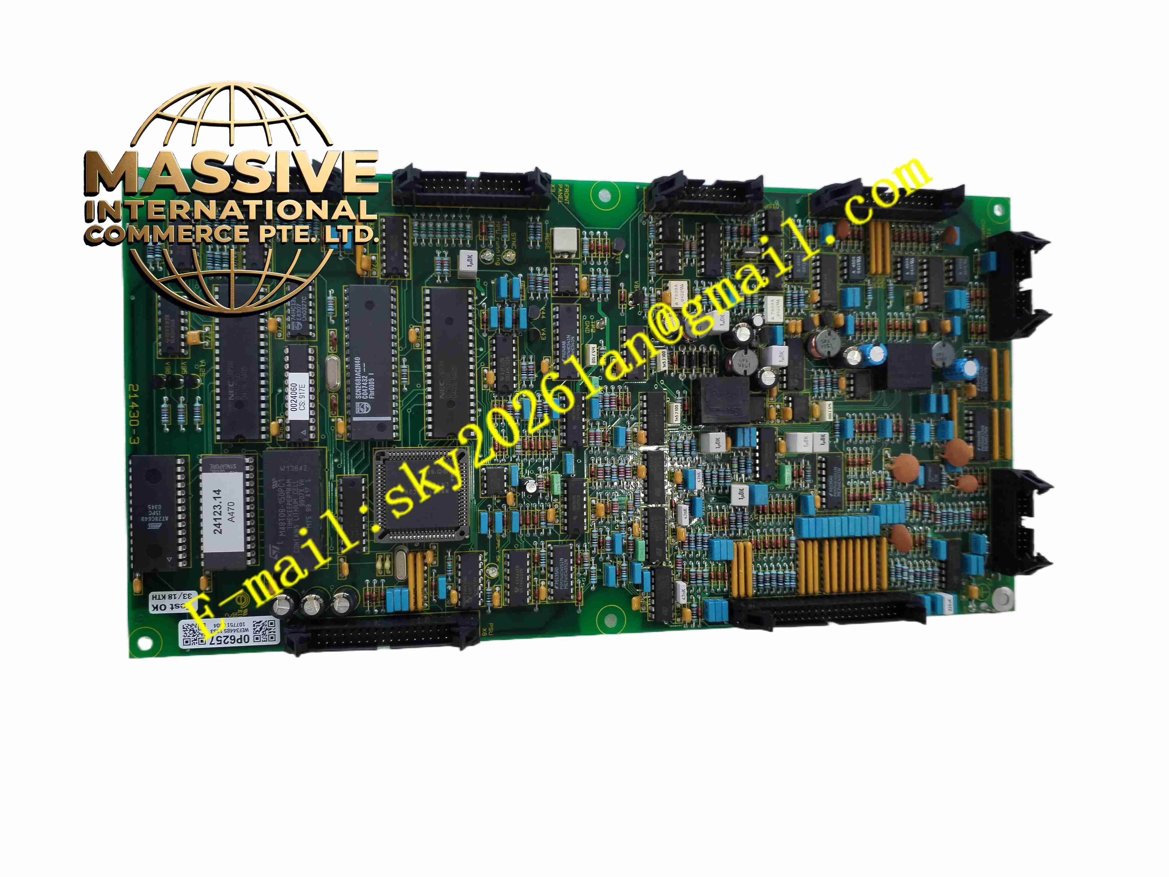
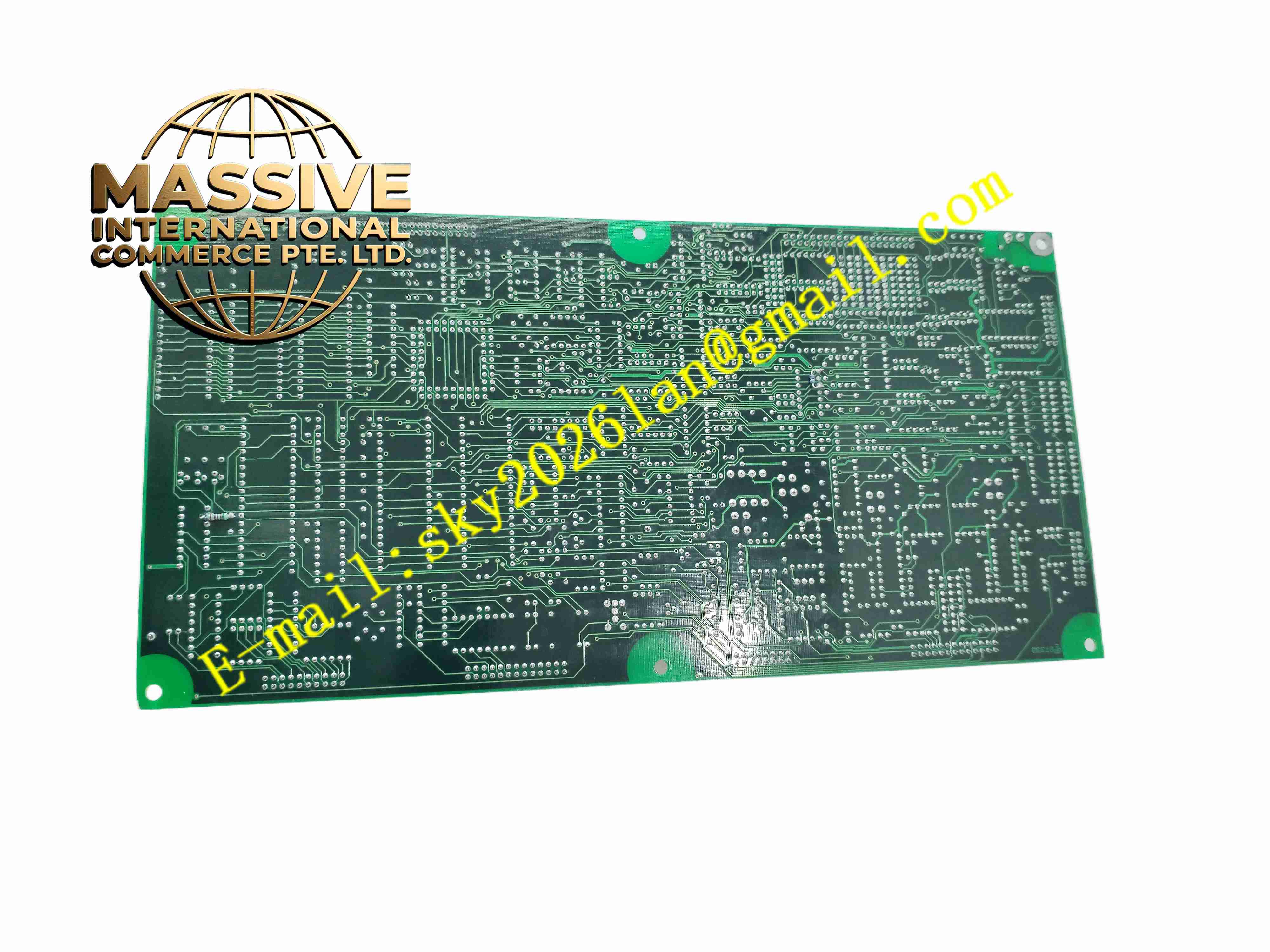
Description
HIMA H4135A
Technical Specifications:
- Power Supply: 24 VDC, -15% to +20%, maximum input current ≤40 mA
- Contact Type: Floating normally open relay contact
- Switching Time: Approx 8 ms closing time, approx 6 ms reset time
- Protection Class: IP20
- Operating Temperature: -25 °C to +60 °C
- Storage Temperature: -40 °C to +85 °C
- Mounting: 35 mm standard DIN rail
- Safety Certification: SIL3, TÜV certified, EN 954-1 Category 3
- Dimensions: 120 mm × 60 mm × 25 mm
- Weight: 180 g
Function Features:
- Electromechanical safety relay with forced guided contacts for safety circuit
- Galvanic isolation between control input side and field contact side
- Fast response for emergency safety trip applications
- Continuous self-monitoring of relay contact status
- LED status indicator for power and relay operating state
- Compact DIN rail housing saves cabinet installation space
- Support series and parallel contact wiring for redundant safety circuits
- Built-in suppression circuit to reduce back EMF from inductive loads
Application Scenarios:
- Oil and gas ESD emergency shutdown solenoid control
- Boiler burner management safety interlock circuits
- Chemical plant safety valve trip control
- Power plant turbine protection interlock
- Refinery overpressure protection safety circuits
Material Composition:
- Housing: Flame retardant thermoplastic plastic
- Relay Core: Guided-contact safety relay with silver alloy contacts
- Internal PCB: FR4 fiberglass circuit board
- Terminals: Tin-plated copper screw terminals
- Spring Components: Stainless steel contact return springs
- Passive Components: Surge suppression diodes, resistors and capacitors
Structural Features:
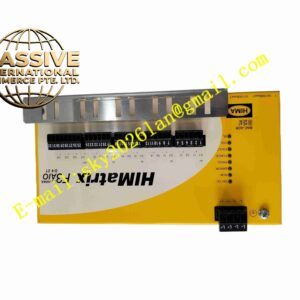
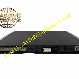
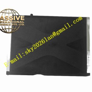
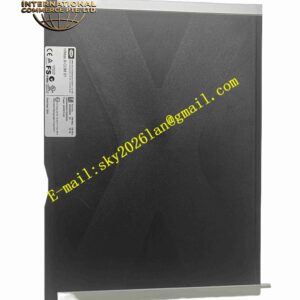
- Slim rectangular DIN rail snap-on housing
- Screw terminal blocks on top and bottom for wiring
- Front panel equipped with status LED and model marking
- Internal separate chambers for control circuit and relay contact chamber
- Rear integrated DIN rail clip for fast mounting and removal
- Forced guided contact mechanical structure inside relay unit
Working Principle: When safety CPU sends enable command, 24 VDC coil energizes. Electromagnetic force pulls armature and closes the normally open safety contact. When safety trip command activates or power supply fails, coil de-energizes. Return spring resets armature and opens safety contact. Forced guided contact structure ensures contact state consistency and prevents contact welding undetected. The module feeds back relay status signal to safety controller for continuous diagnostic verification.
Installation Requirements:
- Mount module on 35 mm DIN rail inside safety cabinet
- Tighten terminal screws with specified torque
- Separate safety contact wiring from low voltage control signal cables
- Use shielded twisted pair cables for safety command wiring
- Maintain cabinet ambient temperature within -25 °C to +60 °C
- Avoid installation locations with heavy vibration and corrosive gas
Usage Notes:
- Verify contact load rating before connecting inductive solenoid loads
- Perform periodic proof test of relay contact integrity according to SIL maintenance schedule
- Disconnect power supply before wiring modification
- Do not exceed rated contact voltage and current
- Inspect contact surface condition during plant shutdown maintenance
- Use external surge protection for large inductive field loads