Description
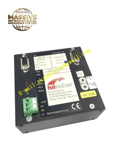
Hilscher PKV‑30‑DPS
Technical Specifications Power supply: 18‑30 VDC, maximum current consumption 0.15 A at 24 VDC PROFIBUS‑DP interface: Isolated RS485, D‑Sub 9‑pin connector, maximum baud rate 12 MBaud Serial interface: Non‑isolated RS232C / RS422 / RS485 configurable, maximum baud rate 19.2 kBaud Memory allocation: 32 KB /128 KB RAM, 128 KB / 512 KB Flash memory Protection rating: IP50 for cabinet‑mount deployment Operating temperature range: 0 °C ~ +50 °C Mechanical dimension: 105 mm × 105 mm × 80 mm Mounting standard: DIN‑EN 50022 DIN rail mounting Indicator LEDs: RDY, RUN, NET, MOD diagnostic status lights
Functional Features Acts as a fully compliant PROFIBUS‑DP slave station on PROFIBUS‑DP bus network. Performs bidirectional data mapping between PROFIBUS‑DP process data objects and serial communication payload. Supports multiple serial communication formats including asynchronous NRZ, synchronous NRZI, SDLC and HDLC protocols. On‑board hardware rotary switch sets PROFIBUS‑DP station address locally without software tool. Multi‑color LED array provides real‑time diagnostic feedback for power status, bus communication state and fault conditions. Supports local serial port diagnostic access for commissioning and troubleshooting.
Application Scenarios Connect legacy serial instruments and weighing systems to PROFIBUS‑DP automation networks. Retrofit serial barcode readers, test‑stand measurement equipment, old‑generation drives and sensors into PROFIBUS‑DP control architecture. Deployed in automotive manufacturing production lines, water treatment plants, chemical process plants, material handling systems and general factory automation sites.
Performance Parameters Guaranteed PROFIBUS‑DP cycle response time matching fieldbus real‑time requirements. Stable serial data framing processing up to maximum 19.2 kBaud serial speed. Galvanic isolation implemented on PROFIBUS‑DP bus side to suppress ground‑loop interference. Deterministic data mapping between bus process image and serial data buffer.
Material Composition Rugged black industrial ABS plastic enclosure, FR‑4 multilayer printed circuit board, metal DIN‑rail mounting hardware, nickel‑plated 9‑pin D‑Sub PROFIBUS connector, screw terminal blocks for power and serial wiring.
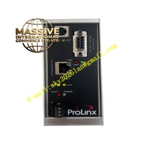
Structural Features Square‑shaped DIN‑rail housing, integrated rear‑side DIN‑rail spring clip, front‑panel rotary address setting switch, front‑facing diagnostic LED indicators, D‑Sub PROFIBUS‑DP connector on one side, screw‑type terminal blocks for power and serial signals on opposite side.
Working Principle PKV‑30‑DPS behaves as a PROFIBUS‑DP slave responding to requests from PROFIBUS‑DP master controller. Process output data received from DP master is converted into serial data frames and transmitted to connected serial device. Data received from serial field equipment is written into PROFIBUS‑DP slave input process image and cyclically transferred to DP master. Internal firmware manages protocol timing, data buffering and format conversion fully autonomously.
Installation Requirements Mount onto standard DIN rail inside IP50 or higher rated industrial control cabinet. Maintain adequate air circulation around unit, avoid stacking heat‑generating modules directly adjacent. Connect PROFIBUS‑DP bus cable to D‑Sub connector following PROFIBUS wiring specification. Terminate PROFIBUS bus segment correctly at physical bus endpoints. Apply 18‑30 VDC power supply with correct polarity. Set PROFIBUS station address via front‑panel rotary switch before power‑on commissioning.
Usage Notes PROFIBUS‑DP side provides galvanic isolation; serial interface remains non‑isolated, so external signal isolation module must be added when ground‑loop risk exists. Operating temperature must stay within 0 °C to +50 °C operating range. Proper PROFIBUS bus termination resistor must be installed at both ends of bus trunk line. Do not remove unit from DIN rail while powered. Verify station address uniqueness across PROFIBUS network to avoid address conflict faults.