



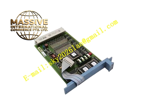
Description
Honeywell 05704-A-0131
Technical Specifications Supports standard industrial fieldbus communication; equipped with extra digital input and digital output channels; rated control power 24VDC; each communication port has ESD protection circuit; operating temperature 0℃ to 60℃; storage temperature -40℃ to 85℃; relative humidity 5% to 95% non-condensing; plug-in auxiliary board; UL and CE certification.
Functional Features It establishes fieldbus communication link between variable frequency drive and upper automation host. It uploads motor speed, current, temperature and fault code to the control system. It receives remote speed setpoint and reset command from host controller. It expands auxiliary discrete output for running, fault and ready status indication. It carries communication error diagnosis and link status monitoring function.
Application Scenarios Fieldbus networking of woodworking production line drive units; remote monitoring interface for rubber and plastic extrusion frequency converters; communication expansion for printing press variable speed drives.
Performance Parameters Communication data refresh cycle matches drive control scan period; bus error detection responds within communication frame period; discrete output switching time meets auxiliary indication requirement.
Material Composition Circuit board adopts FR4 high-temperature flame-retardant PCB with conformal coating; communication connector pins are gold-plated copper alloy; ESD protection and isolation components are industrial semiconductors; fixing hardware is zinc-plated steel; insulating parts use high flame retardant plastic.
Structural Characteristics Plug-in board structure matching drive cabinet slot; front panel with communication port, status LED and auxiliary I/O terminals; rear board-to-board connector for connection with main drive control module; fool-proof keying notch to prevent mismatched insertion; compact layout to save internal drive space.
Working Principle After power-on, the board loads communication firmware and completes hardware self-test. It receives command data sent by upper controller through fieldbus port and forwards valid setpoint and reset signal to main drive module. It collects drive operating parameters and fault information, packages data into bus protocol frame and uploads to the host system. Auxiliary discrete signals are buffered and output through on-board drive circuit.
Installation Requirements Install the board into the reserved expansion slot of variable frequency drive. Use shielded twisted-pair cable for fieldbus wiring. Separate communication cables and high-power motor cables. Tighten connector fixing screws. Ensure cabinet grounding meets EMC requirement.
Usage Notes Set station address and communication parameters according to upper system configuration. Check bus terminal resistor setting for fieldbus network. Wear anti-static wrist strap during installation and replacement. Do not modify on-board firmware without official Honeywell tool.







