



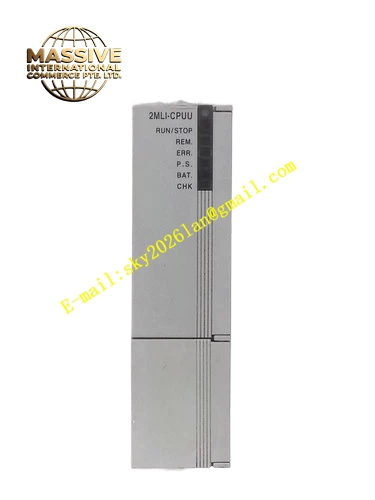
Description
Honeywell 2MLI-CPUU
Technical Specifications
- User program memory: 32 KB
- Data memory: 16 KB
- Logic scan cycle: 0.5 ms per 1 KB program
- Communication ports: 1 RS232 programming port, 1 RS485 Modbus port
- Supported I/O expansion: Up to 16 expansion modules
- Supply voltage: 24 V DC
- Operating temperature: 0 °C to +55 °C
Functional Features Runs IEC 61131-3 ladder logic and function block programs. RS232 programming port connects to engineering laptop for program upload and download. RS485 Modbus RTU port connects to HMI and SCADA systems. On-board LEDs indicate CPU run, stop, fault and communication status. Real-time clock provides event timestamping. Non-volatile program memory, retains logic without battery.
Application Scenarios Small packaging machine sequential control Conveyor system PLC main control HVAC air handling unit master controller Spare part replacement for failed MasterLogic 200 CPUs
Performance Parameters
- Maximum I/O count: 256 discrete points, 64 analog points
- Communication baud rate: 1200 to 115200 bps
- Real-time clock accuracy: ±2 seconds per day
- Data retention: 10 years non-volatile
- Mean time between failures: 300,000 hours
Material Composition ABS flame retardant housing 32-bit industrial microprocessor Flash program memory Real-time clock circuit RS232/RS485 isolation chips DIN rail mounting clip
Structural Features Rectangular DIN-rail mount housing. Front LED array shows run, fault and communication status. Side expansion bus connector links to I/O modules. Bottom terminal block for 24 V power and communication wiring. RS232 programming port on the front panel.
Working Principle After power-up, the CPU loads the user program from flash memory into RAM, entering cyclic scan mode. Each scan cycle reads input states from connected I/O modules, executes ladder logic computation, then writes output values back to I/O modules. The RS485 Modbus port exchanges data with upper HMI. The real-time clock runs scheduled timed events. The watchdog circuit monitors program execution; runaway logic triggers CPU fault and places outputs in safe state.
Installation Requirements Clip the CPU to the leftmost position on the DIN rail. Connect expansion bus to adjacent I/O modules. Wire 24 V DC supply with correct polarity. Connect programming cable to the RS232 port, download the user program. Verify run LED activates, and all I/O modules are recognized.
Usage Notes Reverse 24 V supply polarity damages the CPU power circuit. Program download interrupts running logic; perform during equipment shutdown. RS485 bus requires 120 Ω termination resistor at the far end. Never connect AC power to RS485 terminals, this destroys the isolation chip.







