



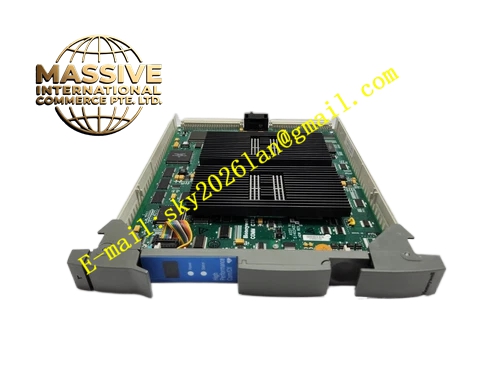
Description
Honeywell 51403422-150
Technical Specifications
- Connected devices: TPS series membrane operator keyboards
- Interface ports: 2 PS/2 style keyboard connectors
- Isolation: 1500 VAC between keyboard side and station backplane
- Backplane interface: TPS operator station VME bus
- Supply power: 5 V DC from backplane
- Operating temperature: 0 °C to +60 °C
- Key scan response latency: ≤10 ms
Functional Features Transmits operator keypress commands to the main processor, fast response for critical control actions. Dual keyboard ports, supports redundant keyboard connection for large control room consoles. On-board optocoupler isolation, blocks ground loop interference between console peripherals and station. On-board LEDs indicate keyboard connection and data activity. Hot swap support, faulty board replacement without station reboot. Compatible with all TPS operator keyboard models.
Application Scenarios Keyboard connection for TPS operator stations Spare part replacement for no-key-response faults in legacy stations Keyboard upgrade retrofits for aging operator consoles Multi-keyboard console setup for shared control room positions
Performance Parameters
- Keystroke response latency: ≤10 ms
- Isolation withstand voltage: 1500 VAC for 1 minute
- Maximum keyboard cable length: 5 meters shielded
- Key scan rate: 100 Hz continuous
- Mean time between failures: 500,000 hours
Material Composition FR4 PCB substrate Keyboard interface controller chip Optocoupler isolation array Gold-plated PS/2 style connectors Metal shielded front panel Gold-plated VME edge fingers
Structural Features Standard VME form factor board. Front panel houses two keyboard connectors. LED array shows keyboard connection and data transfer status. Isolation barrier separates keyboard side and station backplane side. Metal shielded enclosure reduces external EMI pickup.
Working Principle Operator keypress data enters the board via the keyboard connector. The interface controller decodes key scan codes, passing data through optocoupler isolation to the station processor over the VME bus. The dual-port design supports two separate keyboards; keypress data from either port is transmitted to the processor. The monitor circuit checks keyboard connection status; cable disconnection triggers a board fault flag.
Installation Requirements Insert the board into the dedicated peripheral slot in the operator station. Plug keyboard cables into the front panel connectors. Confirm keyboard LEDs activate after station power-up. Test key press response during commissioning, verify all keys register correctly.
Usage Notes Never hot-plug keyboards while station power is on; this damages the keyboard interface chip. Keyboard cables routed near high-voltage wiring cause EMI-induced key bounce. Keyboard cable length must not exceed 5 meters; longer runs cause signal dropout. Optocoupler isolation must remain intact; cutting the shield ground breaks isolation performance.







