



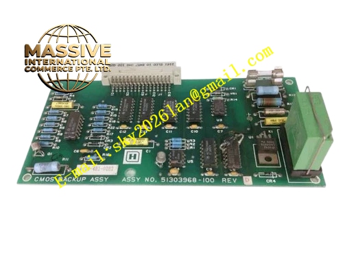
Description
Honeywell 51401491-100
Technical Specifications
- Network type: TPS LCN redundant control network
- Communication rate: 5 Mbps
- Ports: Dual redundant coax BNC interfaces for incoming and outgoing network segments
- Isolation: 1500 VAC between network segments
- Maximum extension distance: 300 meters per repeater hop
- Supply power: 5 V DC from repeater cabinet backplane
- Operating temperature: 0 °C to +60 °C
Functional Features Regenerates attenuated LCN network signals, extends total network length for large plants. Galvanic isolation between network segments, blocks ground loop faults from taking down the entire network. On-board signal quality monitoring, triggers link fault alarm on excessive attenuation. On-board LEDs indicate signal lock on incoming and outgoing network segments. Automatic signal equalization, compensates for cable length differences between segments. Hot swap support, faulty board replacement without network outage.
Application Scenarios LCN network extension for large multi-cabinet control rooms Signal isolation between separate LCN network segments Spare part replacement for weak network signal faults causing packet loss Network retrofit for expanded TPS system installations
Performance Parameters
- Signal regeneration delay: ≤1 μs
- Isolation withstand voltage: 1500 VAC for 1 minute
- Maximum cascade repeater count: 10 hops
- Signal attenuation compensation: Up to 60 dB
- Mean time between failures: 500,000 hours
Material Composition FR4 high-speed PCB substrate Network signal equalizer chip BNC coax connectors Optocoupler isolation circuits Metal shielded front panel Gold-plated edge fingers
Structural Features Standard Eurocard dimensions. Front panel houses four BNC interfaces for two incoming and two outgoing network segments. LED array shows signal lock status per network direction. Metal shielded enclosure contains high-speed bus radiation. Isolation barrier separates incoming and outgoing network circuit areas.
Working Principle Incoming LCN network signals arrive from the upstream segment via the BNC interface. The on-board equalizer amplifies and reshapes attenuated signals, restoring clean digital signal levels. Regenerated signals pass through the isolation barrier, transmitted to the downstream network segment. Bidirectional signal processing repeats signals in both network directions. The signal monitor circuit checks incoming signal strength; excessive attenuation or loss of signal triggers a segment fault alarm.
Installation Requirements Mount the repeater board in the dedicated LCN repeater cabinet slot. Connect upstream network coax cables to the incoming BNC ports, downstream cables to outgoing ports. Check LED status after power-up, confirm signal lock on both network directions. Install 75 Ω termination resistors at network segment endpoints.
Usage Notes Never exceed 10 cascaded repeater hops; excessive delay causes network timing errors. Reversed incoming/outgoing cable connections break network communication. Loose BNC connectors cause intermittent packet loss; tighten connectors during routine maintenance. Network segments must share consistent ground potential on the isolated side to avoid ground loop faults.







