



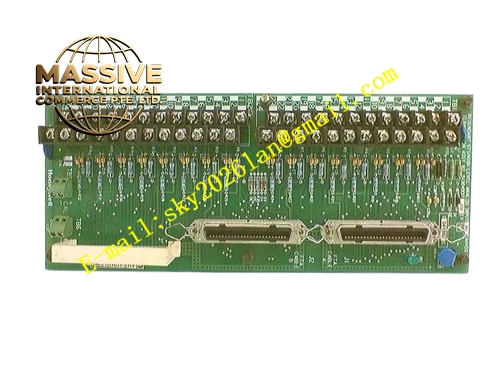
Description
Honeywell 51402497-200
Technical Specifications
- Storage interface: Ultra SCSI 16-bit, 40 Mbps transfer rate
- Connected devices: SCSI hard disk drives, tape backup units
- Backplane interface: TPS operator station VME bus
- Supply power: 5 V DC from station backplane
- Maximum storage capacity: 2 TB per SCSI chain
- Operating temperature: 0 °C to +60 °C
- SCSI ID support: Up to 15 devices per chain
Functional Features High-speed SCSI interface, supports continuous high-volume process data logging. On-board data buffering, absorbs burst write traffic to prevent data loss. Automatic bad block management on storage drives, maintains data integrity. On-board LEDs indicate storage activity, SCSI bus status and fault. Hot swap support, faulty board replacement without station reboot. Compatible with all TPS historian software revisions.
Application Scenarios Historical trend data logging for TPS process systems Alarm event archive storage Spare part replacement for storage interface faults causing data logging failure Historian storage upgrade for TPS operator stations
Performance Parameters
- SCSI data transfer rate: 40 Mbps sustained
- On-board buffer memory: 1 MB
- Data write latency: ≤1 ms
- Mean time between failures: 450,000 hours
- SCSI cable maximum length: 6 meters per chain
Material Composition FR4 high-speed PCB substrate SCSI controller ASIC chip Buffer SRAM chips VHDCI SCSI connector Gold-plated VME edge fingers Metal shielded front panel
Structural Features Standard VME form factor board. Front panel houses the high-density VHDCI SCSI connector. LED array shows storage activity and SCSI bus fault status. Metal shielded enclosure contains high-speed storage signal radiation. Mounting bracket locks to the operator station chassis.
Working Principle The operator station historian software sends process data write commands over the VME bus to the interface board. The board packages data into SCSI protocol frames, transmitting to the connected storage drive. On-board buffer memory absorbs burst write traffic, smoothing data flow to the drive. The SCSI controller manages device addressing and error correction for all devices on the SCSI chain. Read requests for historical trend data retrieve stored data from the drive, returning it to the station processor over the VME bus.
Installation Requirements Insert the board into the dedicated SCSI slot in the operator station. Connect SCSI storage devices to the VHDCI connector, set unique SCSI IDs per device. Install SCSI termination at the far end of the device chain. Confirm the storage drive is recognized in station diagnostic software after power-up.
Usage Notes SCSI chain endpoints require active termination; missing termination causes bus communication failure. Each device on the SCSI chain must have a unique ID; duplicate IDs crash the SCSI bus. Never disconnect SCSI cables while station power is on; this causes storage corruption. SCSI cable length must not exceed 6 meters; longer runs cause signal attenuation.







