



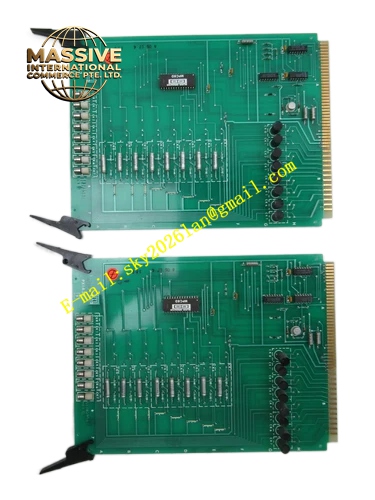
Description
Honeywell 4DP7APX1A32F
Technical Specifications
- Input Signal Range: 4 mA to 20 mA DC
- Channel Number: 32 channels
- A/D Resolution: 16 bit
- Internal Shunt Resistance: 250 Ω
- Isolation: Group isolation 500 VAC
- Operating Temperature: 0 °C to +60 °C
- Backplane Bus: Legacy DCS parallel backplane
- Max Power Draw: 7.5 W
Functional Features Loop break detection for each 4-20mA field circuit. Over-range and under-range signal tagging for each channel. Configurable digital noise filter for stable measurement reading. CRC protected communication between card and controller. Front panel LED indication for power and fault events. Hardware watchdog monitors local measurement logic operation continuously.
Application Scenarios Chemical batch process analog signal acquisition Water treatment plant DCS transmitter input expansion Legacy Honeywell DCS rack spare parts inventory Oil terminal tank level and pressure monitoring system
Performance Parameters
- Full scale accuracy: ±0.12 %
- Channel to channel crosstalk: -63 dB
- Open loop fault detection latency: <120 ms
- Conversion stability under supply voltage variation
Material Composition FR4 UL94 V0 multilayer PCB, precision shunt resistors, ADC chips, optocoupler isolation devices, operational amplifiers, X7R capacitors, metal film resistors, removable screw terminal block, black flame retardant plastic housing, gold plated backplane connector.
Structural Features Plug-in rack card form factor compatible with target DCS rack slot. Detachable wiring terminal block for field wiring maintenance. Front panel LED for power and fault indication. Internal isolation partition between field analog side and logic bus side. Anti-keying notch on card edge.
Working Principle Field current signal converts to voltage over internal shunt resistor. Amplifier conditions voltage signal for ADC sampling. Logic chip validates sample integrity and transmits valid value to controller. Abnormal loop impedance triggers fault status upload. Local watchdog resets card operation if internal logic stops responding.
Installation Requirements Use twisted shielded pair cable for field transmitter wiring. Keep analog cable separated from power and discrete signal wiring. Calibrate zero and span for critical measurement loops after replacement. Verify host controller supports this hardware revision code.
Usage Notes Dual end grounding of cable shield introduces measurement noise. Do not apply AC voltage to input terminals. Do not modify internal filter and sampling circuit components.







