



Description
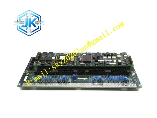
Honeywell 51107144-101
Technical Specifications Core Processor: 32-bit industrial RISC processor Logic Power Supply: 5V DC Power Consumption: 8.2W Operating Temperature Range: 0℃ to 65℃ Storage Temperature Range: -40℃ to 85℃ Isolation Withstand Voltage: 1500V AC Relative Humidity: 5% to 95%, non-condensing Backplane Bus Interface: UCN parallel backplane bus
Functional Features It stores control strategy, PID parameters, setpoint values and event configuration in non-volatile flash memory. It scans all assigned I/O channels at fixed cycle and captures real-time process variables. It supports configurable PID, ratio, cascade, feedforward and custom calculation blocks. It implements watchdog timer circuit to trigger hardware reset for program runaway. It synchronizes timestamp with LCN master clock for alarm and event records. It supports redundant primary/backup HPM handshaking and state synchronization. It uploads diagnostic information, alarm messages and trend data to LCN network.
Application Scenarios Closed-loop control of temperature, pressure, flow and liquid level loops in refining and chemical plants. Batch sequence control for reactor feeding, blending and switching processes. Redundant HPM main control rack replacement and spare inventory for legacy TPS DCS systems. Logic coordination for interlock and safety auxiliary control loops.
Performance Parameters Minimum Control Scan Cycle: 10ms Watchdog Trigger Timeout: 120ms Configuration Data Retention Duration: 10 years without external backup power Backplane Bus Data Transmission Rate: 5Mbps Maximum Supported Control Loop Quantity: 120 loops per board
Material Composition PCB Substrate: High-TG flame-retardant FR-4 multi-layer glass fiber board 32-bit RISC industrial processor chip Non-volatile flash memory and SRAM cache chips Bus transceiver and level conversion integrated circuits Gold-plated back edge fingers Cold-rolled steel front panel with electrostatic anti-corrosion coating High-brightness LED status indicator components
Structural Features Standard pluggable board structure, installed in dedicated HPM processor slot of TDC3000 HPM rack. Front panel carries RUN, FAULT, REDUNDANCY and COMM communication status LEDs. Back edge gold fingers complete electrical connection with rack backplane bus. Analog reference traces and digital logic traces adopt separate routing layout to reduce signal crosstalk. All active chips are covered with acrylic conformal coating for moisture, dust and corrosive gas resistance. Heat dissipation copper pads are reserved on high-power chip areas to stabilize operating temperature.
Working Principle The board obtains 5V DC power supply from HPM rack backplane after rack power-on. The processor completes hardware initialization and reads preloaded control configuration from flash memory. It sends polling commands to UCN I/O cards via backplane bus and receives field measurement data. It executes control algorithm calculation and logic judgment according to preset strategy. It generates control output commands and transmits commands to matched output I/O modules. The watchdog circuit continuously monitors processor running flow. Abnormal program state triggers hardware reset and fault flag recording. It synchronizes operation state with backup HPM board for redundant switching.
Installation Requirements Insert the board vertically into the dedicated HPM processor slot and tighten front panel fixing screws. Confirm backplane pin alignment before full insertion to avoid pin bending. Download control configuration and loop parameters via Honeywell Control Builder software after power-on. Verify loop running status, redundancy switching function and alarm upload on GUS operator station.
Precautions Release static electricity before plugging the board to protect internal processor and memory chips. Do not apply voltage beyond 5V DC specification to backplane interface. Conformal coating damage causes circuit corrosion and intermittent communication failure under high humidity environment. This board cannot operate independently. It must be matched with HPM rack, backplane and corresponding I/O modules. Backplane bus short circuit leads to permanent damage of internal logic circuits.







