



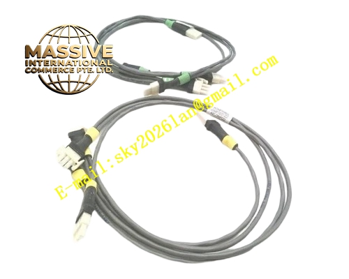
Description
HONEYWELL 51202329-212
Technical Specifications Backplane bus power supply; Multi-channel 24VDC digital input; Per-channel opto-coupler isolation; Hardware contact de-bounce filter; On-board channel open circuit detection; Rack plug-in structure compatible with TDC3000 I/O rack.
Functional Features Collect running status, fault feedback and limit position signals of pumps, fans and valves; Electrically isolate field circuit and control circuit to eliminate ground loop interference; Remove mechanical contact bounce and prevent false interlock trigger; Single channel fault will not affect other normal channels; Upload channel fault and module hardware failure information to controller; Complete power-on self-test automatically.
Application Scenarios Petrochemical plant TDC3000 I/O cabinets; Safety interlock signal acquisition; Valve and motor status monitoring for continuous production units.
Performance Parameters Operating temperature range 0℃ to 60℃; Relative humidity 5% to 95%, non-condensing; High channel isolation voltage; Meet IEC industrial EMC requirements.
Material Composition FR-4 multilayer printed circuit board; Gold-plated backplane edge connectors; Opto-coupler isolation chips; Filter resistors and capacitors; Surge protection components; Anti-static plastic front panel.
Structural Features Rack plug-in card; Front panel with multi-channel LED status indicators; Rear gold fingers connect rack backplane bus; Anti-reverse positioning notch; Model and revision 212 printed on panel.
Working Principle Field 24VDC switch signal enters the submodule via terminal base. Opto-coupler creates electrical isolation between field and control circuit. Hardware de-bounce circuit filters mechanical contact bounce. The module converts on-off state into digital data and transmits to controller through I/O link bus. The diagnostic circuit monitors each input loop continuously and reports open circuit or overvoltage fault to controller.
Installation Requirements Wear anti-static wrist strap during installation and removal; Insert card fully into rack slot and tighten fixing screw; Cabinet protective ground must be qualified; Separate signal cable and power cable routing; Verify hardware version compatibility with controller firmware.
Precautions for Use Do not plug or unplug the module under power-on state; Never connect high voltage AC signal to input channels; Check field contact and wiring when channel fault alarm appears; Inspect terminal screw tightness periodically.







