



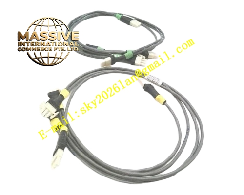
Description
Honeywell 51202329-606
Technical Specifications
- Bus Type: Proprietary parallel DCS backplane bus
- Supported Slot Quantity: Fixed rack slot allocation
- Supply Distribution: +5V, +12V, -12V power rail distribution
- Signal Conditioning: Bus buffer and line termination network
- Operating Temperature: 0°C to +60°C
- Isolation: Power rail filtering isolation
- Board Interface: Edge connector to controller, pin header to rack backplane trace
Functional Features Buffering of address, data and control bus signals to increase bus drive capability. Precision resistor network for bus impedance matching to suppress signal reflection. Power rail LC filtering to reduce switching noise propagating across rack. Bus fault current limiting to isolate shorted slot from entire rack bus. Bus parity signal routing and parity error capture circuit. Passive and active signal conditioning for legacy high speed parallel bus.
Application Scenarios Legacy Honeywell DCS rack backplane communication failure replacement Rack bus signal distortion and intermittent I/O communication fault repair System upgrade rack bus signal integrity improvement Preventative spare part for old process control DCS system annual overhaul
Performance Parameters
- Bus signal rise/fall time conditioning matched to original system timing
- Power ripple attenuation: 40dB minimum at switching noise frequency
- Bus short circuit isolation response: <1µs
- Parity error signal capture resolution: Single bus cycle
Material Composition High TG FR4 multilayer PCB, precision metal film termination resistors, ferrite bead noise filters, electrolytic and ceramic decoupling capacitors, bus buffer logic IC, gold plated edge connectors and pin headers.
Structural Features Flat rectangular printed circuit board mounted at rear side of DCS rack. Multiple pin header connectors aligned with each I/O slot backplane pinout. Edge connector for mating with controller main board. No front panel, fully concealed inside rack rear assembly. Mounting holes fixed to rack metal chassis.
Working Principle Controller bus signals enter this board through edge connector. Buffer IC regenerate bus signal amplitude and drive capacity. Termination resistor network matches characteristic impedance of rack parallel bus traces. Power rails pass through LC filter network before distributing to each slot header. If any slot draws abnormal overcurrent, current limit circuit cuts off that slot power and bus signal path without affecting remaining rack slots.
Installation Requirements Power off rack completely before removing or installing this board. Align all pin headers without offset to avoid bent pins. Secure mounting screws to chassis to establish solid protective ground connection. Verify all bus timing parameters match controller firmware timing specification after replacement.
Usage Notes Do not modify termination resistor values or remove filter components. Handle board with anti-static wristband at all times. Physical pin bending will cause intermittent bus communication fault. Keep rear rack area free of conductive dust accumulation.







