



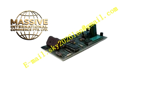
Description
HONEYWELL 51202353-101
Technical Specifications Backplane bus power supply; Multi-channel digital output; Per-channel overload and short-circuit detection circuit; Electrical isolation circuit; On-board hardware self-test circuit; Rack plug-in design compatible with TDC3000 I/O rack.
Functional Features Receive control logic commands from controller and convert instructions into field on-off drive signals; Detect open circuit, short circuit and overload status of each output loop; Isolate faulty channels to prevent fault spreading to the whole module; Transmit channel fault status and module health information to controller; Maintain stable output state during normal system operation; Complete power-on self-check automatically.
Application Scenarios Petrochemical and thermal power plant TDC3000 DCS control cabinets; Safety interlock output loops; Solenoid valve, relay and field status indicator control; Continuous production process discrete control loops.
Performance Parameters Operating temperature range 0℃ to 60℃; Relative humidity 5% to 95%, non-condensing; Comply with industrial EMC standards for control room environment; Long continuous operation life under rated working condition.
Material Composition FR-4 multilayer industrial printed circuit board; Gold-plated backplane edge connectors; Industrial logic processing chips; Surge suppression resistors and capacitors; Anti-static flame retardant plastic front panel.
Structural Features Standard rack plug-in card structure; Front panel fitted with LED indicators for running, communication and channel fault status; Gold fingers on the rear side connect rack backplane bus; Anti-reverse insertion positioning notch; Product model and hardware revision printed clearly on card surface.
Working Principle The module receives digital logic commands from the controller through I/O link bus. Internal logic circuit converts these commands into drive signals for each output channel. When the output channel is activated, the signal transmits to the terminal assembly and triggers field equipment. The on-board diagnostic circuit continuously samples the current of every output loop. Once overload, short circuit or open circuit occurs on any channel, the module locks the faulty channel, sends fault alarm to the controller and keeps other normal channels working continuously.
Installation Requirements Wear anti-static wrist strap during all disassembly and assembly operations; Insert the card vertically and steadily into the designated rack slot, then lock the fixing screw tightly; Ensure cabinet protective grounding system is fully completed and qualified; Verify hardware version matches TDC3000 controller firmware; Guarantee reliable contact between gold fingers and backplane connector.
Precautions for Use Do not plug or unplug the module under power-on state; Keep signal cables separated from high-power power cables; Regularly check panel LED indicator status; Do not exceed rated load for each output channel; Replace spare parts only after verifying complete model and hardware revision.







