



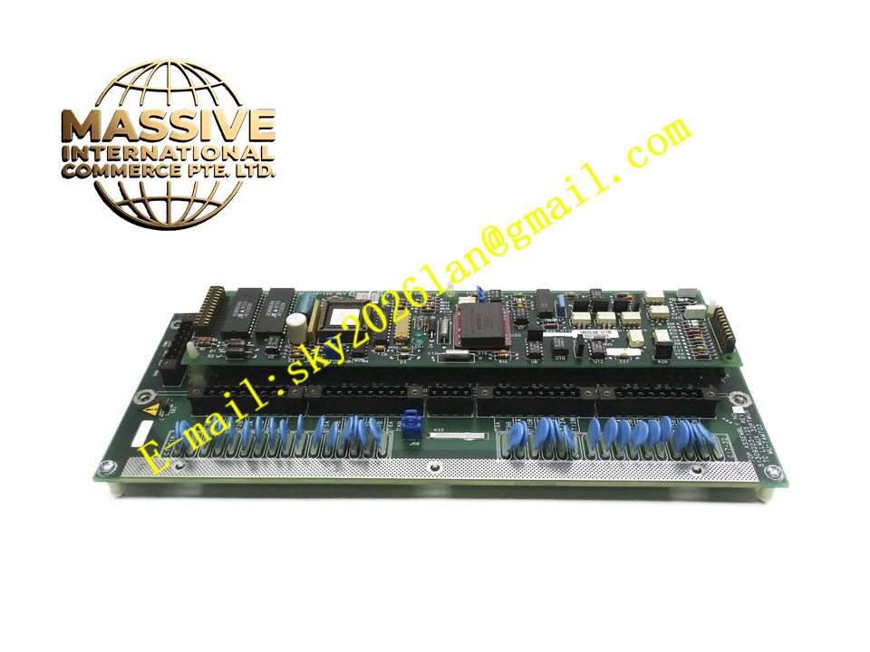
Description
Honeywell 51304163-300
Technical Specifications
- Serial Port Quantity: 4 independent serial channels
- Supported Signal Type: RS232, RS485 configurable per channel
- Backplane Interface: TDC3000 proprietary backplane bus
- Power Supply: 5VDC and 12VDC from rack backplane
- Operating Ambient Temperature: 0°C to +60°C
- Storage Temperature: -40°C to +85°C
- Relative Humidity: 5% to 90% RH non-condensing
- Mounting Type: Plug-in slot installation on TDC3000 main rack
- Certification: UL, CE, RoHS
- Baud Rate Range: 300bps to 38400bps configurable
Functional Features It transmits TDC3000 process data to external serial devices through each channel. It receives command and status data from third-party serial instruments and forwards valid data to TDC3000 main processor. It supports independent baud rate, data bit, stop bit and parity configuration for each channel. It carries built-in serial port surge protection and optical isolation circuit. It carries front panel LED indicators for power, channel active and fault. It supports hot swap replacement in non-critical rack configuration. It adopts large data buffer to avoid packet loss under high-frequency transmission. It uploads serial port communication fault and frame error count to TDC3000 operator station.
Application Scenarios TDC3000 multi-analyzer serial communication interface rack Petrochemical plant online gas analyzer data collection cabinet Refinery process data transmission to multi-channel chart recorder Power plant auxiliary instrument serial data interconnection rack Chemical plant third-party PLC multi-point serial communication gateway
Performance Parameters
- Isolation Rating: 1500VAC between serial port and logic circuit
- Mean Time Between Failures: 780000 hours
- ESD Immunity: 8kV contact discharge
- Maximum Cable Length: 15m for RS232, 1200m for RS485
- Single Channel Buffer Depth: 2048 bytes
Material Composition FR4 flame retardant conformal coated multilayer PCB Four independent UART controller chips RS232 and RS485 transceiver chips Optocoupler isolation components for each channel TVS surge suppression diodes Backplane bus transceiver chip Gold plated edge connector for backplane Metal front panel with extraction handle, LED indicators and terminal block Removable plastic terminal block for serial wiring
Structural Features Standard paddle card form factor. Front panel integrates removable serial wiring terminal block and grouped LED indicators plus extraction handle. Rear gold plated edge connector mates with rack backplane power and control bus. Each serial channel has independent isolation barrier and transceiver circuit. Anti-key notch prevents reverse insertion into rack slot. Locking clip secures module firmly after installation. Internal PCB layout separates serial signal circuit and high-speed backplane bus circuit to reduce crosstalk.
Working Principle After power on, the module initializes serial port parameters for each channel according to engineering configuration. It receives parallel data from backplane bus, converts parallel data into serial format and sends to external device via selected serial standard. It receives serial signal from external device, converts serial data to parallel format and transmits valid data to main processor. If overvoltage, signal short circuit or frame check error is detected on serial terminal, protection circuit cuts off channel output and fault flag generates. Fault information is uploaded to operator station.
Installation Requirements Wear anti-static wrist strap before inserting module into vacant serial communication slot of rack. Lock extraction handle after alignment. Connect shielded twisted pair cable to serial terminal block. Configure baud rate, parity and signal standard for each channel in engineering software. Power on rack and verify channel active LED. Test communication with target external instrument one by one. Ground serial cable shield at single point on instrument cabinet side. Separate serial cable from high voltage power cable in wiring duct.
Usage Notes Do not connect RS232 port to long-distance multi-drop bus. Install 120Ω terminator resistor at the end of each RS485 bus. Check terminal screw tightness periodically under vibration environment. Recalibrate serial communication parameters after replacing external instrument. Replace module when multiple serial channels fail to transmit data.







