



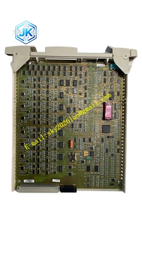
Description
Honeywell 51309152-175
Technical Specifications
- Brand: Honeywell
- Part Number: 51309152-175
- Product Type: Analog Output IOP Module
- Associated Family: MC-PAOX03
- Channel Count: 8 channels
- Applicable Platform: Honeywell DCS/process control hardware platform
- Mounting Method: Standard rack plug-in installation
- Signal Type: Analog output
- Power Supply: Powered by system cabinet or backplane
- Operating Environment: Industrial control room cabinet environment
- Certification: Subject to nameplate and official documentation
Functional Features
- Provides 8-channel analog output signal generation for process control.
- Converts internal control data into standard field analog signals.
- Supports multiple output ranges including 4-20 mA, 0-20 mA, 0-10 mA, 1-5 V, 0-5 V, and 0-10 V.
- Works with system racks, backplanes, power supplies, and controller modules.
- Provides status indication, fault monitoring, and system diagnostics.
- Suitable for system maintenance, fault replacement, and spare inventory.
Application Scenarios
- Honeywell DCS control station maintenance
- Replacement of failed analog output modules
- Planned shutdown maintenance activities
- Chemical, power, metallurgical, pharmaceutical, and other process industry plants
- Control cabinet hardware upgrade or expansion
- Emergency spare replacement for legacy DCS systems
Performance Parameters
- Output Signal Types: 4-20 mA (load resistance ≤ 550 Ω), 0-20 mA (load resistance ≤ 550 Ω), 0-10 mA (load resistance ≤ 1.1 kΩ), 1-5 V (load resistance ≥ 250 kΩ), 0-5 V (load resistance ≥ 250 kΩ), 0-10 V (load resistance ≥ 4 kΩ, special custom).
- Accuracy: ±0.2% FS.
- Sampling Period: 1 second.
- Internal Flash Memory Capacity: 64 M Byte.
- Recording Capacity: 12 channels with 64 M Byte storage.
- Operates within a Honeywell DCS hardware platform.
- Performance depends on system version, installed firmware, and configuration.
Material Composition
- Industrial-grade printed circuit board
- Metal or engineering plastic front housing
- Backplane connector
- Status indicator LEDs
- Terminal or interface connectors
- Fixing latches or mounting hardware
- Protective coating on circuit components
Structural Features
- Rack-mounted plug-in design.
- Front panel carries status indicators, labels, and interface markings.
- Rear connector mates with the system backplane.
- Compact structure suitable for control cabinet installation.
- Part number 51309152-175 is marked on the module label.
- Compatible with the corresponding Honeywell I/O rack and card family.
Working Principle
As an analog output IOP module, 51309152-175 receives control data from the DCS controller and converts it into standard analog output signals for field devices such as control valves, actuators, and other analog input instruments. The module monitors its own operating status and reports faults or alarms to the control system when abnormal conditions occur. It provides 8 independent output channels, each configurable for the required signal range and load conditions.
Installation Requirements
- Confirm the system is in a safe maintenance state before handling the module.
- Verify that 51309152-175 matches the original module and system configuration.
- Confirm the correct slot position and rack compatibility.
- Insert the module smoothly and avoid forcing the connector.
- Ensure the module is fully seated and locked in place.
- Verify power supply, grounding, and communication links after installation.
- Check system alarms, module status, and output signal behavior after replacement.
- Perform functional verification when required by maintenance procedures.
Precautions for Use
- Follow plant maintenance and safety procedures before replacement.
- Do not substitute with an unverified part number.
- Avoid electrostatic discharge, moisture, dust, and mechanical shock.
- Record alarm history, slot position, and original module information before removal.
- Store spare modules in anti-static and dry packaging.
- If the module shows burn marks, connector damage, or abnormal indicators, do not install it without further testing.
- Final confirmation must be based on Honeywell official manuals and the physical module label.







