



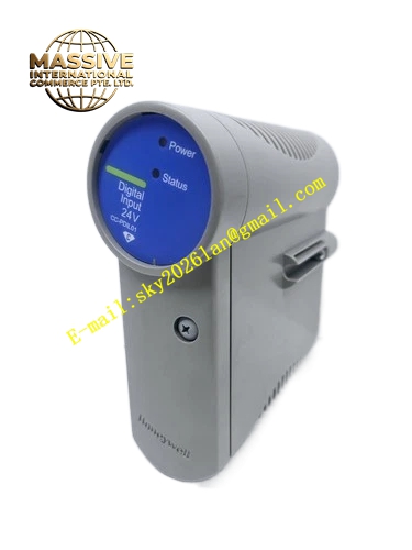
Description
Honeywell 51401551-601
Technical Specifications
- Rated Supply Voltage: 24 VDC
- Rated Operating Current: 1.8 A
- Airflow Volume: 42 CFM
- Fan Speed Range: 2800 RPM to 3600 RPM
- Speed Monitoring Signal: Pulse frequency feedback signal
- Fault Output Form: Isolated dry contact alarm relay
- Operating Temperature: 0 °C to +60 °C
- Storage Temperature: -40 °C to +85 °C
- Relative Humidity: 5 % to 95 % non-condensing
- Vibration Resistance: 1 g, 10 Hz to 150 Hz
- Hot Swap Support: Yes
- Mechanical Dimension: Standard rack plug-in form factor matching FSC chassis
Functional Features Built-in hall effect sensor continuously detects real-time rotational speed of each fan. Independent fault relay sends alarm signal to SIS logic solver when fan stall, speed drop or power loss occurs. Balanced airflow channel directs cooling air across high heat density TMR processor boards. Reverse polarity protection circuit prevents permanent damage during wrong wiring connection. Filter mesh blocks conductive dust and fiber debris from entering SIS internal circuit zone. Front panel LED indicator shows power status, normal running condition and fan fault state. Multiple fan units operate in parallel to maintain cooling capacity when single fan fails.
Application Scenarios SIL3 ESD safety shutdown cabinet thermal control Boiler burner management BMS rack cooling system Offshore oil and gas platform Safety Manager SIS cabinet Chemical plant high-risk process interlock SIS overhaul spare replacement Refinery emergency trip control cabinet preventive maintenance
Performance Parameters
- Fan service life: 50000 hours at 40 °C ambient temperature
- Alarm trigger threshold: Speed below 2200 RPM
- Relay contact rating: 24 VDC, 0.5 A resistive load
- Response delay for fault detection: Less than 200 ms
- Air pressure static head: 0.35 inch H2O
- Acoustic noise level: 52 dB at full speed
Material Composition Main frame: Black UL94 V0 glass filled nylon plastic Fan impeller: Reinforced thermoplastic PBT Motor bearing: Double ball bearing assembly Filter mesh: Stainless steel woven mesh PCB control board: FR4 multilayer flame retardant substrate Surge protection: TVS diodes and ferrite beads Terminal connector: Tin plated copper alloy screw terminal block
Structural Features Front pull tab and locking latch for quick extraction from rack slot. Internal airflow baffle guides cooling air toward critical hot components. Separate wiring cavity isolates low voltage fan power cable from safety signal wiring. Integrated anti-keying notch prevents installation into incompatible I/O card slots. Sealed bearing design reduces contaminant ingress from industrial cabinet atmosphere. Front panel transparent window protects LED indicators against mechanical scratch.
Working Principle 24 VDC power energizes brushless DC fan motors to generate directional cooling airflow. Hall sensor on each fan outputs pulse signal proportional to rotational speed to onboard monitoring circuit. Monitoring IC compares measured speed against preset threshold. If speed falls below limit or fan stalls, relay contact changes state and fault alarm signal transmits to SIS controller. LED indicator changes color to notify local maintenance personnel of cooling failure. Parallel redundant fan layout ensures cooling continuity after single fan failure.
Installation Requirements Verify SIS rack power can remain energized before hot swap operation. Align guide rails and push the module fully until locking latch engages. Route 24 VDC power cable and fault signal cable separately from safety I/O wiring. Tighten terminal screws to torque range of 0.4 N·m to 0.6 N·m. Confirm airflow direction matches rack specified front-to-back cooling path. Reset SIS fault alarm in Safety Builder software after replacement completes.
Usage Notes Do not remove stainless steel filter mesh during normal operation. Clean filter mesh every three months in high dust industrial environment. Do not block air inlet or outlet openings of the fan assembly. Fan bearing degradation triggers speed drift and pre-fault alarm. Static wristband must be worn during handling of internal control PCB.







