



Description
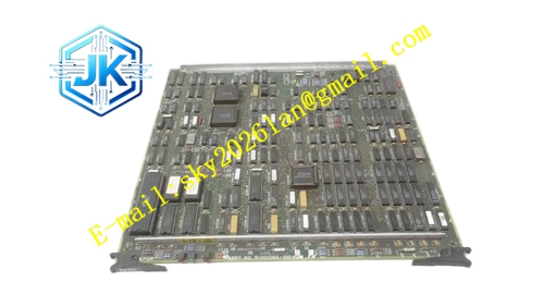
Honeywell 51402471-201
Technical Specifications Channel Count: 8 universal analog input channels Supported Signal Type: 4-20mA DC, 0-5V DC, J/K/T/E/R/S/B thermocouple, PT100/PT1000 RTD Logic Power Supply: 5V DC Field Loop Power: 24V DC for current transmitters Power Consumption: 7.8W Operating Temperature Range: 0℃ to 60℃ Storage Temperature Range: -40℃ to 85℃ Isolation Withstand Voltage: 1500V AC per channel Relative Humidity: 5% to 95%, non-condensing
Functional Features Each channel supports independent signal type configuration through software. It provides channel-to-channel galvanic isolation. It integrates on-board cold junction compensation sensor for thermocouple channels. It supports lead resistance compensation for 3-wire and 4-wire RTD channels. It executes wire break, short circuit and over-range fault detection and alarm. It supports hot swap operation. It stores channel type, scaling and filter parameters in non-volatile memory. It uploads real-time measurement value and fault status to DCS system.
Application Scenarios Mixed signal acquisition of pressure transmitters, temperature thermocouples and RTD sensors in one I/O rack. Multi-parameter monitoring for reactor, heat exchanger and distillation auxiliary equipment. Retrofit project for old TPS racks with mixed instrument signal types. Replacement and spare stocking for universal analog input cards in legacy TPS UCN racks.
Performance Parameters ADC Resolution: 16 bit Full Scale Accuracy: ±0.15% FS Cold Junction Compensation Accuracy: ±0.2℃ Channel Scan Period: 3ms per channel Wire Break Detection Resolution: 0.5μV for thermocouple, 0.2Ω for RTD
Material Composition PCB Substrate: High-TG flame-retardant FR-4 multi-layer glass fiber board, low-level signal shielding zoning layout High-resolution low-noise ADC conversion chip On-board platinum cold junction compensation sensor Universal signal conditioning and switching circuit components Channel isolation optocoupler array Gold-plated back edge fingers Gold-plated field terminal block contacts Cold-rolled steel front panel with electrostatic spray coating
Structural Features Standard European pluggable card structure, installed in dedicated universal analog I/O slot of UCN I/O rack. Front panel is equipped with run indicator light, individual channel fault indicator lights and general fault indicator light. Field wiring terminals are arranged on the side panel, marked for current, voltage, thermocouple and RTD wiring. Low millivolt signal traces adopt full shielding layout to avoid external electromagnetic noise coupling. Each channel is equipped with independent isolation barrier.
Working Principle Field signals from different types of sensors enter the module through shielded cables. The signal switching circuit selects matched conditioning circuit according to software configuration. The isolation circuit separates field loop and internal logic circuit. The conditioning circuit filters noise and amplifies weak signal. The ADC chip converts analog signal into digital value. The FPGA chip executes corresponding compensation and linearization algorithm based on configured signal type. It converts raw digital data into standard engineering value and sends data and fault information to rack IOP processor through backplane bus. It records wiring fault events with time stamp.
Installation Requirements Insert the module vertically into the dedicated universal analog I/O slot of UCN rack and tighten front panel fixing screws. Connect field sensor wires to the corresponding terminal ports following selected signal type marking. Use matched thermocouple extension wire or RTD cable for temperature signal wiring. Ground the shielding layer at the module side only. Download channel signal type, scaling and filter parameters from Control Builder software after power on. Verify measurement accuracy and wire break alarm function on the HPM diagnostic screen.
Precautions Release static electricity before plugging the module to protect high-precision low-level ADC circuit. Do not connect high voltage signals to input terminals. Different signal types cannot share the same cable tray without isolation. Thermocouple wiring polarity reversal leads to wrong temperature reading. Re-configure channel signal type only after stopping related control loops.







