



Description
Honeywell 51401524-100
Technical Specifications Channel Count: 32 digital output channels, matched with FTA Supported Output Type: 24V DC sinking/sourcing drive, relay coil drive Logic Power Supply: 5V DC Field Loop Power: 24V DC Power Consumption: 6.7W Operating Temperature Range: 0℃ to 60℃ Storage Temperature Range: -40℃ to 85℃ Isolation Withstand Voltage: 1500V AC per channel group Relative Humidity: 5% to 95%, non-condensing
Functional Features It supports independent channel fail-safe state configuration. It executes output loop short circuit detection and fuse blown fault alarm when paired with matched FTA. It supports hot swap operation within powered UCN I/O rack. It stores output state, pulse width and interlock configuration parameters in non-volatile memory. It uploads real-time output status and channel fault information to DCS diagnostic console. It supports group interlock suppression logic for safety protection. It provides output feedback signal collection for loop supervision.
Application Scenarios Indicator light and alarm horn drive for local control panel. Solenoid valve control for batch feeding and sequence switching. Relay drive for auxiliary interlock and equipment protection logic. Replacement and spare stocking for aging digital output multiplexer cards in legacy TPS UCN racks.
Performance Parameters Output Command Response Latency: ≤0.9ms Pulse Output Adjustable Width: 10ms to 10000ms Fault Detection Resolution: 0.12mA Configuration Data Retention Time: 10 years without external power supply
Material Composition PCB Substrate: High-TG flame-retardant FR-4 multi-layer glass fiber board Digital logic FPGA processing chip Signal drive and level conversion chips Group isolation optocoupler array Gold-plated back edge fingers Gold-plated ribbon cable connector contacts Cold-rolled steel front panel with electrostatic spray coating
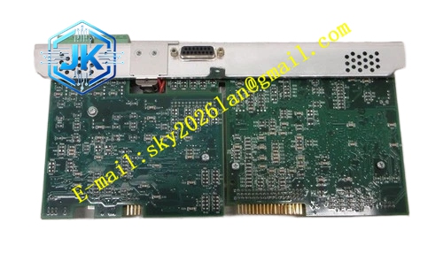
Structural Features Standard European pluggable card structure, installed in dedicated digital output multiplexer slot of UCN I/O rack. Front panel is equipped with run indicator light, general fault indicator light and group status indicator lights. Ribbon cable connector is arranged on the side panel for connection to matched DO FTA termination boards. Digital signal traces adopt differential routing layout to restrain external electromagnetic interference. Each group of 8 channels is divided into independent isolation zone to prevent fault cross transmission.
Working Principle The module receives digital output commands from rack IOP processor through backplane bus. The FPGA chip parses command frame, executes interlock logic judgment and generates drive signal. The drive signal passes through optocoupler isolation circuit and transmits to DO FTA board via ribbon cable. The FTA board drives field loads according to the signal. The supervision circuit collects feedback signal from field loop and sends back to this multiplexer module. When short circuit or fuse failure is detected, the module locks output state, marks channel fault and uploads alarm event with time stamp.
Installation Requirements Insert the module vertically into the dedicated digital output multiplexer slot of UCN rack and tighten front panel fixing screws. Use factory specified ribbon cable to connect this module with matched DO FTA termination boards. Confirm ribbon cable pin definition and insertion direction before power supply switch-on. Download channel fail-safe mode and interlock configuration from Control Builder software after power on. Verify output action and fault alarm function on the HPM diagnostic screen.
Precautions Release static electricity before plugging the module to protect internal logic and isolation chips. This module must work with matched DO FTA termination board, it cannot directly drive field loads independently. Do not connect AC high voltage signals to the matched FTA output terminals. Loose ribbon cable connection causes intermittent output loss and false fault alarm. Set proper fail-safe state for safety interlock channels to avoid unsafe action upon module failure.







