



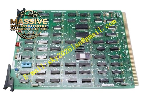
Description
Honeywell 51450991-001
Technical Specifications
- Terminal count: 64 field termination channels
- Conductor range: 12–22 AWG field wire
- Integrated protection: Per-channel TVS surge protection
- Grounding bar: 100 mm tinned copper grounding bus
- Mounting: DIN rail or panel mount
- Operating temperature: 0 °C to +60 °C
- Insulation rating: 600 V
Functional Features Organized field cable termination, reduces wiring confusion during maintenance. Per-channel TVS surge protection, clamps transient voltage before signals reach I/O cards. Integrated copper grounding bar, collects all cable shield grounds for single-point bonding. Terminal labeling silk-screened per channel, matches I/O point identification. Detachable terminal blocks, simplifies field wiring modifications. Shielded cable clamp points for incoming cable armor.
Application Scenarios Field cable entry termination for TPS I/O cabinets Surge protection retrofit for outdoor field cable runs Wiring organization upgrade for aging I/O cabinets New TPS cabinet field wiring assembly
Performance Parameters
- Surge clamping voltage: 30 V for signal channels
- Terminal tightening torque: 0.5 Nm
- Insulation resistance: ≥1000 MΩ
- Grounding bar resistance: ≤0.1 mΩ
- Current rating per terminal: 5 A continuous
Material Composition High-density screw terminal blocks Tinned copper grounding bus TVS surge protection diode array Steel mounting panel PVC channel labeling strips Cable armor clamps
Structural Features Rectangular steel mounting panel. Two rows of terminal blocks arranged for 64 channel wiring. Copper grounding bar mounted along one edge. Cable entry gland plate at the panel bottom. Silk-screen channel labels aligned with each terminal.
Working Principle Incoming field cables pass through the cabinet entry glands, routed to the termination panel terminals. Field signals pass through per-channel TVS protection, then run to individual FTA boards via internal cabinet wiring. Cable shields connect to the integrated copper grounding bar, bonded to the cabinet protective ground. The panel acts as an organized transition point between plant field cabling and internal I/O card wiring.
Installation Requirements Mount the panel at the cabinet field cable entry point. Connect incoming cable shields to the grounding bar, bond the bar to cabinet ground. Wire field signals to labeled terminals, route internal cabinet wiring to corresponding FTA boards. Tighten all terminal screws to rated torque.
Usage Notes Never daisy-chain multiple panel grounding bars; each panel must bond directly to cabinet ground. TVS diodes require replacement after a severe surge event. Terminal blocks must be fully seated; loose connections cause intermittent signal dropout. Cable armor must be grounded at the panel entry point to provide EMI shielding.







