



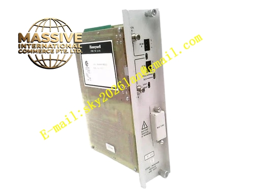
Description
Honeywell 620-0021
Technical Specifications
- Channel Quantity: 8 isolated analog input channels
- Input Signal Range: 4 mA to 20 mA
- Resolution: 16-bit ADC
- Measurement Accuracy: ±0.1 % full scale
- Channel Isolation: 500 VAC group reinforced isolation
- Loop Supply: 24 VDC loop power output per channel for two-wire transmitters
- Backplane Interface: IPC620 I/O Link backplane bus
- Operating Temperature: 0 °C to +60 °C
- Power Consumption: 5.5 W maximum
- Hot Swap Support: Yes
Functional Features Built-in 24 VDC loop supply powers two-wire pressure, temperature and flow transmitters. Per channel loop break detection triggers fault alarm when current drops below 3.8 mA. Overrange and underrange detection identifies transmitter calibration drift or wiring fault. Programmable scaling converts raw ADC count directly into engineering unit value. Front panel LED shows module power, bus communication and group fault state. All analog data frames use CRC checksum for communication integrity verification. Input signal low pass filter suppresses high frequency industrial noise on field loop.
Application Scenarios Pressure transmitter and temperature RTA transmitter signal acquisition Vortex flow meter and magnetic flow meter analog 4-20mA signal interface Liquid level transmitter measurement input for tank inventory control Water treatment plant analog instrument signal collection IPC620 PLC analog measurement channel spare replacement
Performance Parameters
- ADC conversion update rate: 10 Hz per channel
- Isolation withstand voltage: 500 VAC for 60 seconds
- Temperature drift: ±25 ppm / °C full scale
- Common mode rejection ratio: 85 dB minimum
- Loop short circuit protection current limit: 28 mA per channel
Material Composition FR4 multilayer PCB, 16-bit high precision ADC chip, instrumentation amplifier, optocoupler isolation devices, precision sampling resistors, TVS surge diodes, decoupling ceramic and tantalum capacitors, gold plated backplane edge connector, UL94 V0 flame retardant plastic front panel.
Structural Features Standard eurocard plug-in form factor compatible with IPC620 rack slot. Rear gold edge connector mates with IPC620 backplane bus. Internal isolation barrier separates field current loop circuit and internal logic circuit. Front panel LED array shows power, TX/RX activity and group fault status. Anti-keying notch prevents reversed insertion. Analog signal traces are shielded and separated from digital bus traces.
Working Principle Field 4-20 mA current flows through precision sampling resistor and converts to voltage signal for ADC sampling. Low pass filter removes high frequency noise before analog-to-digital conversion. Onboard FPGA reads digital value, applies configured scaling formula and checks current against loop break threshold. Valid process value and diagnostic flag are packed into I/O Link frame and transmitted to IPC620 CPU. Short circuit on field loop activates hardware current limiting circuit.
Installation Requirements Field instrument cable uses twisted shielded pair cable, shield grounded only at cabinet termination point. Separate analog signal cable from high voltage power cable in cable tray. Configure range, engineering unit and filter time in IPC programming software. Verify 24 VDC loop voltage output with multimeter before connecting transmitters. Confirm firmware compatibility between module and IPC620 controller.
Usage Notes Dual point shield grounding introduces common mode noise and measurement drift. Do not inject voltage signal directly into current input terminals. Two-wire transmitter loop resistance must stay within transmitter specification limit. Precision sampling resistors cannot be replaced with general purpose resistors.







