



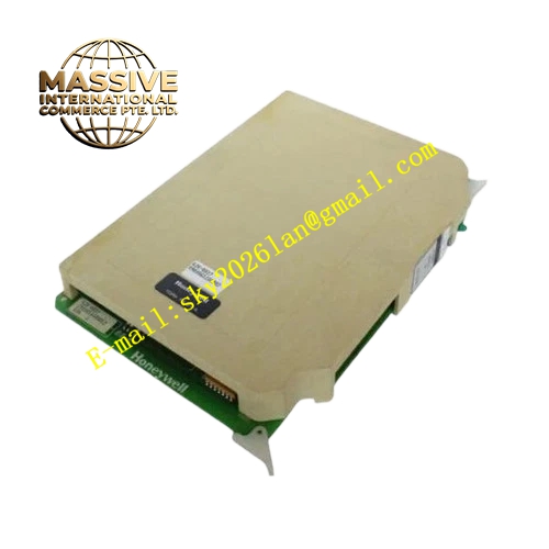
Description
Honeywell 620-0022
Technical Specifications
- Channel Quantity: 8 isolated analog output channels
- Output Signal Range: 4 mA to 20 mA
- Resolution: 16-bit DAC
- Output Accuracy: ±0.1 % full scale
- Channel Isolation: 500 VAC group reinforced isolation
- Maximum Load Resistance: 600 Ω per channel
- Backplane Interface: IPC620 I/O Link backplane bus
- Operating Temperature: 0 °C to +60 °C
- Power Consumption: 6 W maximum
- Hot Swap Support: Yes
Functional Features Per channel hardware current limiting and short circuit shutdown protection. Output readback circuit samples actual output current and compares it against commanded value to detect load failure. Configurable fail-safe state holds output at predefined value when I/O Link communication is lost. Front panel LED indicates module power, bus communication and group fault. CRC checksum validates all incoming command frames from controller. Slew rate limit prevents rapid output jump that damages field actuators. Fault timestamp uploads to PLC event log for maintenance tracing.
Application Scenarios Control signal output for pneumatic control valve positioner Variable frequency drive speed setpoint control Duct damper actuator positioning signal output Chemical continuous process PID control loop analog output IPC620 PLC analog control channel spare replacement
Performance Parameters
- DAC update rate: 10 Hz per channel
- Isolation withstand voltage: 500 VAC for 60 seconds
- Temperature drift: ±30 ppm / °C full scale
- Settling time: Less than 250 µs for full scale step change
- Output ripple: Less than 8 µA peak to peak
Material Composition Multilayer FR4 PCB, 16-bit DAC chip, precision current output driver, optocoupler isolators, current sampling precision resistors, TVS surge suppression diodes, decoupling capacitors, gold plated backplane edge connector, flame retardant plastic front panel with extraction handle.
Structural Features Standard plug-in eurocard form factor matching IPC620 rack slot. Rear gold edge connector mates with IPC620 backplane bus. Internal isolation barrier separates low voltage logic circuit and field analog output circuit. Front panel LED array shows module health and communication status. Anti-keying notch prevents reversed insertion. Power driver components are placed with dedicated copper thermal pad for heat dissipation.
Working Principle I/O Link bus transmits digital setpoint command from IPC620 CPU. Onboard logic verifies CRC checksum and sends value to DAC chip. DAC converts digital value into analog reference voltage. Current driver circuit converts reference voltage into stable 4-20 mA output current. Sampling resistor continuously monitors actual output current. If measured current deviates from target value beyond tolerance range, load fault flag is generated and uploaded to controller. When communication is lost, channel locks at pre-configured fail-safe current value.
Installation Requirements Field output wiring uses twisted shielded pair cable, single point shield grounding inside control cabinet. Confirm total loop resistance including cable and actuator stays below 600 Ω. Inductive load requires external freewheeling protection diode across actuator terminals. Set fail-safe value and slew rate limit in IPC configuration software. Verify output current with multimeter during commissioning.
Usage Notes Do not short output terminals continuously, hardware latch cuts off channel after short circuit detection. Do not connect AC voltage to analog output terminals. Long cable runs increase loop resistance and reduce available driving capacity. Do not modify onboard current feedback sampling circuit.







