



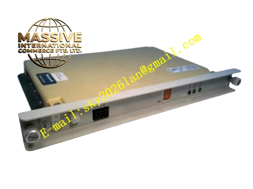
Description
Honeywell 620-0044
Technical Specifications
- Backplane Bus: IPC620 proprietary I/O Link bus
- Network Interface: Single RJ45 10BASE-T Ethernet port
- Network Rate: 10 Mbps half-duplex / full-duplex auto negotiation
- Supported Protocol: Modbus TCP server and client mode
- IP Assignment Mode: Static IP configured by DIP switch and software
- Isolation Rating: 1500 VAC isolation between backplane circuit and Ethernet circuit
- Supply Power: 5 VDC from rack backplane
- Operating Temperature: 0 °C to +60 °C
- Power Consumption: 5.3 W maximum
- Hot Swap Support: Yes
Functional Features Auto negotiation of 10 Mbps Ethernet link speed and duplex mode. Built-in Modbus TCP protocol stack supporting server and client switching. Link pulse detection circuit judges network cable break and link disconnection. Front panel LED indicators show power, Ethernet link, data transmit and receive status. TCP connection timeout and abnormal connection reset function avoid network deadlock. Data forwarding between I/O Link bus and Ethernet network carries CRC integrity check. IP address and subnet mask can be locked through DIP switch to prevent accidental modification. Network fault event is recorded with millisecond timestamp and uploaded to PLC event log.
Application Scenarios IPC620 PLC access to factory Ethernet SCADA monitoring network Ethernet HMI remote connection for IPC620 control system Cross-cabinet Modbus TCP data sharing between multiple IPC620 controllers Network transformation of old IPC620 racks originally using serial communication Network communication spare replacement for industrial water treatment and chemical control cabinet
Performance Parameters
- Maximum concurrent TCP connection number: 8 connections
- Single packet forwarding delay: Less than 600 μs
- Network isolation withstand voltage: 1500 VAC for 60 seconds
- Maximum transmission distance: 100 m using standard CAT5 twisted pair cable
- Packet error rejection rate: 100 % for damaged TCP packets
Material Composition FR4 multilayer high TG PCB, Ethernet PHY transceiver chip, FPGA protocol conversion chip, network isolation transformer, optocoupler isolation devices, TVS surge suppression components, gold-plated backplane edge connector, RJ45 metal shielded connector, UL94 V0 flame retardant plastic front panel.
Structural Features Standard eurocard plug-in form factor matching IPC620 rack slot. Shielded RJ45 port is arranged on front panel with four network status LED lights. Internal network isolation transformer separates industrial Ethernet side and control backplane circuit. DIP switch group is hidden under dust-proof cover on front panel for static IP configuration. Anti-keying notch prevents wrong insertion into serial communication module slot. Differential Ethernet signal traces adopt length matching layout to reduce signal distortion.
Working Principle CPU sends read-write command and process data to the module through I/O Link backplane bus. FPGA chip unpacks proprietary bus data and repackages it into Modbus TCP Ethernet frame, which is sent out through PHY chip and RJ45 port. When Ethernet receives Modbus TCP request from remote host, the module verifies frame integrity, converts valid request into I/O Link bus command and transmits to CPU. Network monitoring circuit detects link pulse signal continuously. Once the network cable is disconnected or link partner disappears, link fault flag is generated and reported to controller.
Installation Requirements Power off the rack before module installation and DIP switch setting. Use shielded CAT5 or higher grade twisted pair network cable for connection. Set static IP address, subnet mask and gateway in IPC configuration software. Match Modbus TCP slave address and register mapping table between module and host. Separate Ethernet cable and high voltage power cable in cable laying path. Check link LED and network communication register after power on and commissioning.
Usage Notes This module only supports 10 Mbps Ethernet and cannot run at 100 Mbps rate. Static IP conflict on the same network segment will lead to communication failure. Do not connect the module directly to public internet without network firewall protection. Shield layer of network cable must be single-point grounded inside control cabinet. Do not pull RJ45 connector violently to avoid internal PHY circuit damage.







