



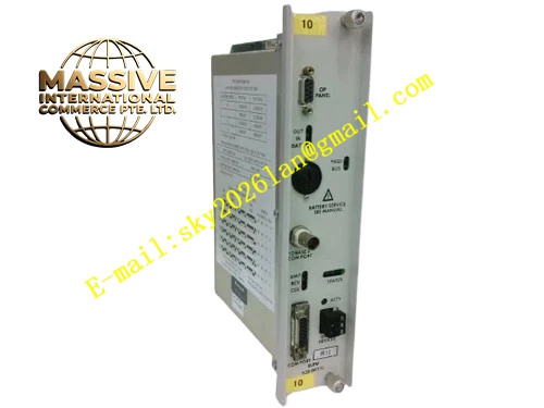
Description
Honeywell 620-0073
Technical Specifications
- Backplane Bus: IPC620 proprietary I/O Link bus
- Supported Control Loops: 8 independent PID regulatory loops
- Control Algorithm: Standard PID, PI, PD, on-off control configurable per loop
- Setpoint Range: Configurable within full engineering unit range of linked I/O channels
- Update Cycle: 50 ms minimum loop execution cycle
- Isolation Rating: 1000 VAC isolation between loop logic circuit and field I/O side
- Supply Power: 5 VDC from rack backplane
- Operating Temperature: 0 °C to +60 °C
- Power Consumption: 6.4 W maximum
- Hot Swap Support: Yes
Functional Features Each PID loop runs independently with separate gain, integral and derivative parameter sets. Automatic/manual/cascade mode switching with bumpless transfer. High and low process variable alarm, deviation alarm and rate-of-change alarm per loop. Windup protection for integral action to prevent saturation during actuator saturation. Front panel LED indicators show module health, bus link and individual loop alarm status. Loop parameter and mode can be modified online through IPC configuration software. All loop setpoint, process variable and output values carry CRC integrity check. Loop fault diagnostic data uploads separately to CPU diagnostic registers.
Application Scenarios Continuous temperature, pressure and flow closed-loop control for chemical reactors Boiler water level and steam pressure regulation in power auxiliary control systems Cooling tower and heat exchanger temperature control loops Water treatment pH and conductivity automatic regulation Offload replacement of PID calculation tasks from IPC620 main CPU
Performance Parameters
- Loop calculation precision: 0.05 % of full scale
- Bumpless transfer deviation: Less than 0.1 % full scale
- Alarm response latency: Less than 150 ms
- Common mode noise rejection: 82 dB minimum
- Parameter save retention: 10 years minimum in non-volatile memory
Material Composition Multilayer FR4 UL94 V0 PCB, industrial FPGA control logic chip, non-volatile flash memory chip, optocoupler isolation array, precision metal film resistors, TVS surge suppression diodes, tantalum filter capacitors, gold-plated backplane edge connector, UL94 V0 flame retardant plastic front panel.
Structural Features Standard eurocard plug-in dimension matching IPC620 rack slot. Front panel LED group displays module power, bus communication and loop alarm signals. Internal isolation barrier separates control logic area and field I/O signal area. DIP switch bank for base configuration sits behind dust-proof plastic cover. Anti-keying notch prevents mis-insertion into communication or digital I/O slots. Separate ground plane layout isolates analog reference traces from high-speed digital traces.
Working Principle The module reads analog measurement values from assigned input channels via I/O Link backplane bus at each control cycle. Each independent PID engine compares measured process variable against active setpoint and computes corrective output value according to configured algorithm. Bumpless transfer logic aligns manual output value with automatic calculation value during mode switch. Alarm logic compares process value against threshold limits and triggers alarm flags when thresholds are breached. Calculated output values are sent to assigned analog output modules through the backplane bus. All loop status and alarm information is packaged and transmitted to the main CPU.
Installation Requirements Power off the rack before installation and initial loop configuration. Map each loop to designated analog input and analog output channels inside configuration software. Tune PID parameters on-site according to actual process response characteristics. Verify bumpless transfer function between auto and manual mode during commissioning. Separate field instrument cables from high voltage power wiring. Check loop alarm trigger action by injecting test signal to linked analog input.
Usage Notes Loop parameter modification during critical continuous production will change control response. Integral windup protection must remain enabled for control valves with hard travel limits. This module does not execute discrete interlock logic, only continuous regulatory control. Do not connect external analog signals directly to the module front panel terminals. Do not replace onboard reference resistors which determine PID calculation precision.







