



Description
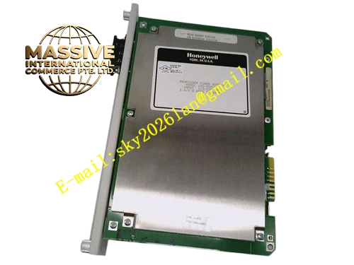
Honeywell 620-3032
Technical Specifications
- Rated supply voltage: 24 V DC
- Operating current: 0.3 A
- Airflow rating: 85 CFM
- Rotational speed: 3200 RPM
- Fault alarm: Passive dry contact, triggers on fan stop
- Operating temperature: 0 °C to +60 °C
- Protection rating: IP20, for cabinet interior installation
- Noise level: 42 dB(A)
Functional Features Dual ball bearing fan, long continuous operating service life. Integrated Hall speed sensor, continuously monitors fan rotational speed. When fan speed drops below threshold or fan stops, the dry alarm contact actuates, sending fault signal to the control system. Removable dust filter at air intake, blocks dust from entering the cabinet interior. Hot swap compatible, single fan replacement does not interrupt redundant cabinet ventilation.
Application Scenarios Main forced ventilation for standard IPC620 control cabinets High-availability redundant power rack cooling Cabinet internal fan replacement for aged units with bearing noise or speed drop Spare cooling component for legacy IPC620 cabinet maintenance
Performance Parameters
- Bearing rated service life: 60000 hours at 40 °C ambient
- Alarm trigger speed threshold: <2000 RPM
- Static pressure: 0.12 inch H2O
- Startup voltage: 18 V DC
- Surge tolerance: ±2 kV contact electrostatic discharge
Material Composition Modified PBT engineering plastic fan blades Dual ball bearing brushless DC motor Flame retardant ABS plastic fan frame Nylon mesh dust filter Galvanized steel mounting bracket Sealed reed alarm relay
Structural Features Square standard fan size, with fixed mounting bracket. Dust filter clip-fitted to the air intake side. Wiring leads include 24 V power wires and alarm contact wires. Air guide shroud directs vertical airflow across the cabinet module area. Mounting hole pattern matches standard control cabinet fan cutout dimensions.
Working Principle 24 V DC supply drives the brushless fan motor, spinning the blades to generate directional airflow. External cool air passes through the dust filter to remove particulates, enters the cabinet interior, picks up heat from operating boards and power supplies, and exhausts through the cabinet top vent. The Hall sensor continuously measures fan rotational speed; when speed drops below threshold, the on-board reed relay contact actuates, outputting a fan fault dry contact signal to the cabinet temperature monitoring system.
Installation Requirements Mount the fan on the cabinet air intake side, airflow direction flows from outside to inside the cabinet. Keep intake and exhaust paths unobstructed, do not block airflow with cabling. Wire alarm contact signals into the cabinet temperature monitoring loop. Match 24 V power polarity per marking, reversed connection stops fan operation and damages the motor. Remove and clean the dust filter quarterly to maintain airflow.
Usage Notes Clogged dust filter reduces cooling airflow, clean filter every 3 months. Stuck fan bearings trigger fault alarm, replace with matched fan unit promptly. Do not insert hands into moving fan blades, risk of mechanical injury. Inspect wiring insulation regularly, damaged insulation causes short circuit and fan stop.







