



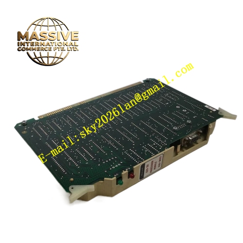
Description
Honeywell 620-3033
Technical Specifications
- Ground bus material: Tin-plated copper
- Number of terminal positions: 12 M4 screw connection points
- Ground resistance: ≤0.1 Ω
- Continuous current rating: 20 A
- Insulation mounting plate: Flame retardant epoxy board
- Operating temperature: -20 °C to +70 °C
- Mounting: Screw-fixed to inner cabinet wall
- Surge discharge capacity: 10 kA (8/20 μs waveform)
Functional Features Tin-plated copper bus bar provides low contact resistance, no oxidation over long service life. Epoxy insulation plate fully separates the copper bus from the metal cabinet frame, implementing true single-point grounding. MOV connected between signal ground and protective ground, high resistance during normal operation, conducts surge current during transient events. Zoned layout separates protective ground, shielding ground and functional ground connection points, prevents cross-interference between different grounding circuits. Each terminal position includes spring lock washer, cables remain tight under long-term vibration. Dedicated main ground position for connection to plant ground grid.
Application Scenarios IPC620 cabinet equal potential grounding connection Single-point shield grounding for instrument signal cables Protective ground for cabinet doors, fan units and mounting brackets Static and surge current discharge ground path Standard grounding component for new control cabinet assembly
Performance Parameters
- Bus bar cross section: 30 mm × 3 mm
- Contact resistance: ≤5 mΩ
- Insulation withstand voltage: 1500 VAC, insulation plate to ground
- Anti-corrosion performance: Tin plating resists salt spray oxidation
- Screw tightening torque: 1.2 N·m
Material Composition Tin-plated copper ground bus bar Epoxy flame retardant insulation mounting plate Zinc oxide MOV Stainless steel M4 connection screws, spring washers Flame retardant nylon wire identification labels Powder-coated steel mounting bracket
Structural Features Long copper bus bar fixed to the epoxy insulation plate. 12 screw positions zoned by grounding type. Large dedicated main ground terminal at one end, connected to plant ground grid. Insulation plate mounted directly to the cabinet wall, the copper bus remains fully isolated from the metal frame. Silk-screen labeling identifies each grounding zone.
Working Principle All cabinet ground connections, including metal enclosure, instrument cable shields, and power supply ground terminals, are terminated to the copper bus bar. The bus bar connects to the plant ground grid via a single point. MOV between signal ground and protective ground stays high-resistance during normal operation, blocking ground loop current flow. During lightning or switching surge events, the MOV conducts instantly, diverting surge current to ground through the low-resistance copper bus, protecting sensitive electronic components.
Installation Requirements Maintain full electrical isolation between the copper bus and cabinet metal frame, no accidental contact. Use minimum 6 mm² yellow-green ground wire for main connection to the plant ground grid. Add spring lock washers under every ground terminal, prevent loosening from vibration. Route different grounding circuits in separate zones, do not mix connections on a single screw. Test ground resistance after installation, confirm value ≤0.1 Ω.
Usage Notes Never directly mount the copper bus against the cabinet frame, this creates multi-point grounding and introduces ground loop interference. Aged MOV breakdown connects signal ground directly to protective ground, replace MOV periodically. Check terminal screw tightness annually, loose connections cause elevated ground resistance and protection failure. Sand off oxidation on copper bus surface without damaging the tin plating layer.
今天 15:16







