



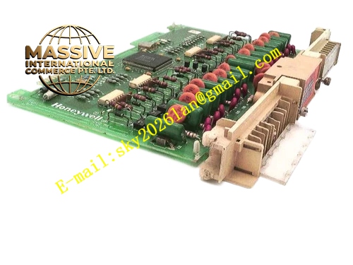
Description
Honeywell 621-1151
Technical Specifications
- Channel count: 8 analog output channels
- Output signal type: 4–20 mA DC current
- Resolution: 12-bit DAC
- Channel isolation: 500 VAC group isolation
- Maximum load impedance: 750 Ω
- Backplane interface: 621 parallel I/O bus
- Operating temperature: 0 °C to +60 °C
- Hot swap support: Yes
Functional Features Per-channel independent output readback sampling, monitors actual output current against command value for circuit diagnosis. Configurable fail-safe output value, triggers preset safe output during communication failure. Per-channel short-circuit protection, automatically limits current on output short circuit. Output slew rate limit setting, prevents rapid valve travel spikes. On-board LED indicates module power, communication and channel fault status. Output command frames carry CRC checksum for transmission integrity.
Application Scenarios Control valve positioner drive for pressure and flow regulation Analog indicator and chart recorder drive signals PID loop analog output execution channel Process control actuator signal output Spare analog output channel replacement for legacy 621 systems
Performance Parameters
- Output accuracy: ±0.1% full scale
- DAC update rate: 50 Hz per channel
- Isolation withstand voltage: 500 VAC for 60 seconds
- Short circuit recovery: Automatic after fault removal
- Fault switchover response time: ≤50 ms
Material Composition FR4 PCB substrate 12-bit DAC chip Output drive operational amplifier Optocoupler isolation array Precision reference voltage chip TVS surge protection diodes Gold-plated backplane edge finger connector UL94 V0 flame retardant plastic front panel
Structural Features Standard Eurocard dimensions, inserts into the 621 rack I/O slot. Front screw terminals for field instrument connection. Physical isolation barrier separates backplane logic circuit and analog output drive circuit. Anti-keying notch prevents reversed insertion into digital input slots. Reference voltage circuit layout is isolated from high-speed digital traces.
Working Principle The CPU sends digital setpoint values to the module via the backplane bus. The DAC chip converts the digital value to an analog voltage or current signal after amplification and drive circuit conditioning. The readback sampling circuit continuously monitors actual output value; deviation between measured feedback and command triggers a channel fault alarm. When communication is lost, the module outputs the pre-configured fail-safe level. Short circuit detection circuit triggers current limiting protection during overcurrent events.
Installation Requirements Match output signal type to the actuator input rating. Set fail-safe value and slew rate in configuration software. Use shielded twisted pair cable for output wiring. Calibrate zero and span during commissioning.
Usage Notes Excessive load impedance causes 4–20 mA output deviation. Never connect AC power to analog output terminals. Slew rate set too high causes valve impact and process fluctuation.







