



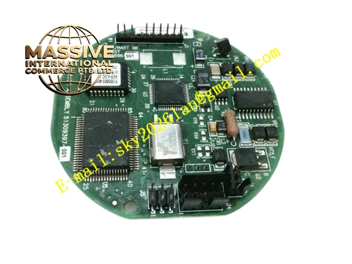
Description
Honeywell 82407020-001
Technical Specifications
- Compatible module: NIM network interface module
- Port count: 3 UCN redundant network ports, 1 LCN bus mating connector
- Power supply: 5 V DC backplane supply
- Termination: 75 Ω UCN network terminal matching
- Operating temperature: 0 °C to +60 °C
- Mounting: Rack slot fixed installation
Functional Features Dual redundant network ports, supports redundant UCN network communication. On-board 75 Ω termination resistors, eliminates signal reflection on high-speed network runs. Gold-plated contacts, long-term insertion contact reliability without oxidation. On-board power filtering circuit, delivers clean 5 V DC supply to the NIM. ESD protection on all network ports, diverts static charge during cable plug-in. Silk-screen labeling marks Network A and Network B port positions.
Application Scenarios Mounting base for TDC3000 NIM module Spare part replacement for oxidized backplane contacts and network connection faults Repair of NIM network communication dropouts and packet loss Interface unit assembly for new TDC3000 cabinet builds
Performance Parameters
- Network communication rate: 5 Mbps
- Signal reflection attenuation: ≥-30 dB
- Gold finger plating thickness: 30 microinch
- Insulation resistance: ≥1000 MΩ
- Network bit error rate: ≤10^-9
Material Composition FR4 high-speed PCB substrate Gold-plated network connectors Precision termination resistor network High-speed common mode choke ESD protection diodes Gold-plated edge finger backplane connector
Structural Features Long rectangular high-speed PCB structure. Front face houses two redundant coaxial network ports. Rear gold fingers mate directly to the NIM main module. Mounting holes on board edge lock to cabinet bracket. Impedance-controlled trace layout matches UCN network 75 Ω characteristic impedance.
Working Principle The backplane connects to the NIM main module via rear gold fingers, routing A and B UCN network signals out to front coaxial ports. On-board termination resistors absorb signal reflection at the network end, ensuring intact high-speed signal waveforms. The power filtering circuit removes ripple from backplane 5 V DC supply before delivering power to the NIM. ESD protection components divert static charge arriving via network cables.
Installation Requirements Press the NIM module evenly into the backplane slot, confirm gold fingers are fully seated. Connect redundant Network A and B cables to the corresponding coaxial ports. Ground the backplane reliably to cabinet protective ground. Test network communication after installation, confirm no signal reflection errors in diagnostic software.
Usage Notes Never remove on-board termination resistors; mismatched impedance causes network reflection and communication failure. Loose coaxial connectors cause intermittent packet loss; tighten connectors during routine maintenance. Clean oxidized gold fingers with a rubber eraser, never sand the gold plating layer.







